1_NXT Conveyor(1.0)E.pdf - 第40页
2. Open ConveyorTestTool and select the [I/O check] tab. 3. Turn CY004 and CY009 ON and then OFF to carry out the sensitivity adjustment for the conveyor panel pass check sensors. 4. Select the [Transport] tab and click …
8. Click [Load] and select [Ln1_HiSpeedUclmp_chk].
9. Ensure that the conveyor is clamped, and then click [Continuous] to execute the
command.
10. Adjust speed controller 5 until the response data reads M25.2.
11. Lock the speed controller, and then confirm that the response data still reads M25.2.
Summary of lane1 commands
12. Refer to the following table and repeat the adjustments for the lane2 conveyor.
2.9 Checking the loading time
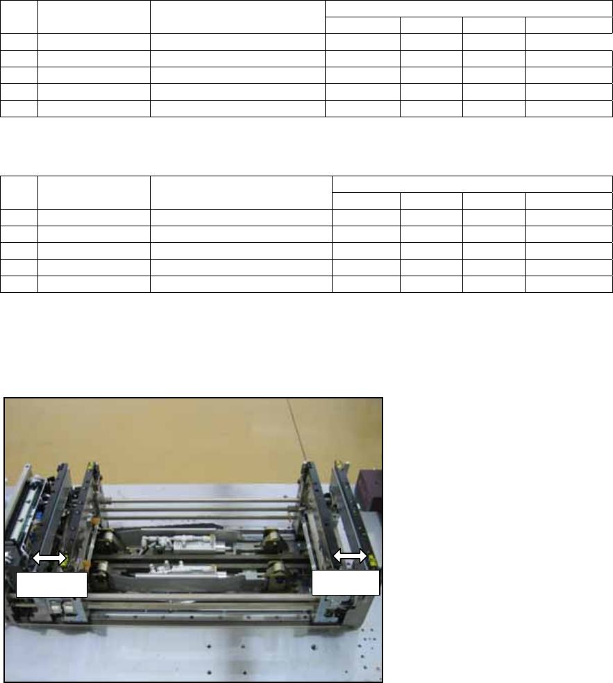
1. Set the width of both lanes to 50mm as shown in the following photo.
Response Data No. Lane 1 Speed
Controller
Send Command
Normal Fast Slow Abnormal
1 Clamp (slow) Ln1_LoSpeedClmp_chk M25.2 M10.2 M11.2 M12.2
3 IN unclamp Ln1_INUclmp_chk M25.2 M10.2 M11.2 M12.2
4 Clamp (fast) Ln1_HiSpeedClmp_chk M25.2 M10.2 M11.2 M12.2
5 Unclamp (fast) Ln1_HiSpeedUclmp_chk M25.2 M10.2 M11.2 M12.2
Response Data No. Lane 2 Speed
Controller
Send Command
Normal Fast Slow Abnormal
1 Clamp (slow) Ln2_LoSpeedClmp_chk M25.5 M10.5 M11.5 M12.5
2 Unclamp (slow) Ln2_LoSpeedUclmp_chk M25.5 M10.5 M11.5 M12.5
3 IN unclamp Ln2_INUclmp_chk M25.5 M10.5 M11.5 M12.5
4 Clamp (fast) Ln2_HiSpeedClmp_chk M25.5 M10.5 M11.5 M12.5
5 Unclamp (fast) Ln2_HiSpeedUclmp_chk M25.5 M10.5 M11.5 M12.5
50mm
50mm
NXT Repair Training Textbook
Conveyor Unit
FK-9F98-43-0E
Edition 1.0 38 / 46 FUJI Machine Mfg. Co., Ltd.
2. Open ConveyorTestTool and select the [I/O check] tab.
3. Turn CY004 and CY009 ON and then OFF to carry out the sensitivity adjustment for
the conveyor panel pass check sensors.
4. Select the [Transport] tab and click [Load] – [LoadingTime_M3PanelSizeChng].
5. Click [Send 5] to teach the conveyor that the board length is 50mm.
6. Click [Load] – [LoadingTime_RvsStd_Ln1_DoubleConv_chk].
7. Ensure that the lane1 conveyor is unclamped and that the backup plate or the block
jigs (PM24380) are in place.
8. Put the smallest panel (L50 x W50 x t0.4mm) in the center of lane1.
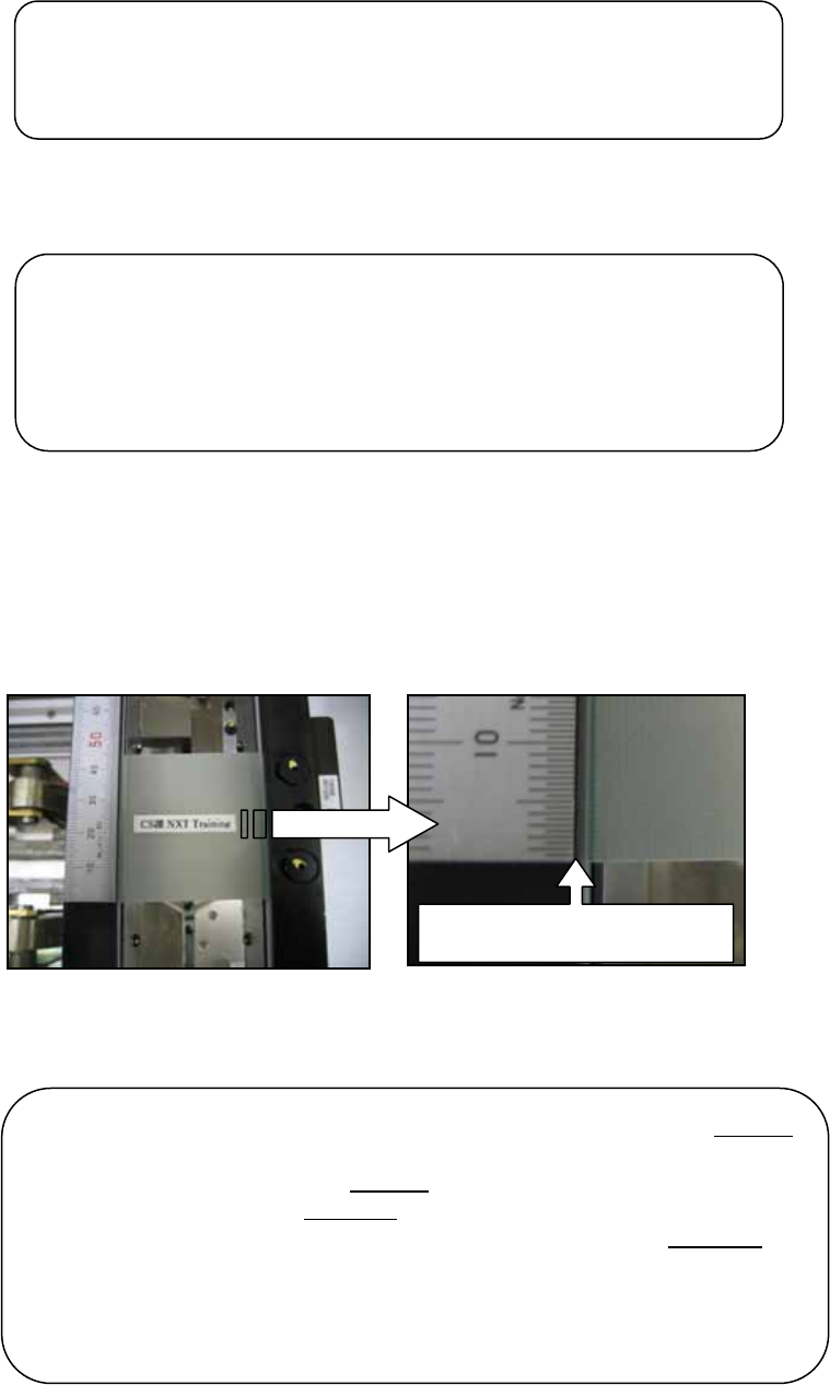
9. Place a scale on the conveyor rail and line it up with the edge of the panel.
10. Click [Continuous] and the panel is transported from the center to the end of the
conveyor, and then back to the center where it is clamped. Use the scale to check that
the panel always returns to the same position in the center of the conveyor.
Line up the edge of the scale
with the ed
g
e of the
p
anel
Note: if the panel travels to the center of the conveyor from the left end
of the conveyor it should stop in the same position the next time it
travels to the center from the left end
. If the panel travels to the center
of the conveyor from the right end
of the conveyor it should stop in the
same position the next time it travels to the center from the right end
.
The stopping position of the panel when it is traveling from the left end
may be slightly different to the stopping position when it is traveling
from the right end. This is normal. Only compare the stopping position
of the panel when it is traveling from the same end.
Note: if you turn OFF the CID power then you must teach the
conveyor the board length again. Turn ON the CID and load
the [LoadingTime_M3PanelSizeChng] command in the
ConveyorTestTool. Click [Send 5] to teach the conveyor that
the board length is 50mm.
Note: if you change the conveyor width at any time you must
carry out the sensitivity adjustment for the conveyor panel pass
check sensors again.
NXT Repair Training Textbook
Conveyor Unit
FK-9F98-43-0E
Edition 1.0 39 / 46 FUJI Machine Mfg. Co., Ltd.
11. Confirm that the response data reads M25, and then click [Cancel] to stop the
conveyor operation.
12. Click [Load] – [LoadingTime_RvsStd_Ln2_chk] and repeat the procedure for lane2.
13. Set the width of both lanes to 280mm.
14. Select the [I/O Check] tab and turn CY004 and CY009 ON and then OFF to carry out
the sensitivity adjustment for the conveyor panel pass check sensors.
15. Select the [Transport] tab and click [Load] – [LoadingTime_M3PanelSizeChng].
16. Click [Send 3] to teach the conveyor that the board length is 250mm.
17. Click [Load] – [LoadingTime_RvsStd_Ln1_DoubleConv_chk].
18. Ensure that the lane1 conveyor is unclamped and that the backup plate or the block
jigs (PM24380) are in place.
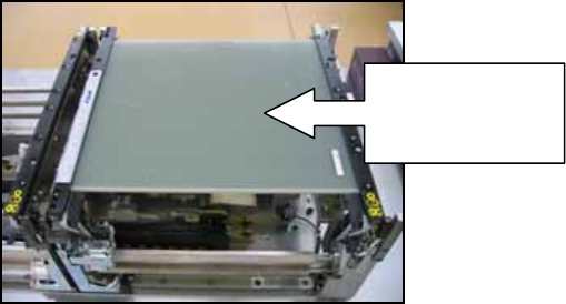
19. Put the medium panel (L250 x W280 x t6mm) in the center of lane1.
20. Place a scale on the conveyor rail and line it up with the edge of the panel.
21. Click [Continuous] and use the scale to check that the panel always returns to the
same position in the center of the conveyor.
22. Confirm that the response data reads M25, and then click [Cancel] to stop the
conveyor operation.
23. Click [Load] – [LoadingTime_RvsStd_Ln2_chk] and repeat the procedure for lane2.
24. Set the width of lane1 to 510mm.
25. Select the [I/O Check] tab and turn CY004 ON and then OFF to carry out the sensitivity
adjustment for the conveyor panel pass check sensors.
26. Click [Load] – [LoadingTime_RvsStd_Ln1_DoubleConv_chk].
Put the medium
panel in the
center of lane1
NXT Repair Training Textbook
Conveyor Unit
FK-9F98-43-0E
Edition 1.0 40 / 46 FUJI Machine Mfg. Co., Ltd.