1_NXT Conveyor(1.0)E.pdf - 第8页
3. Glue the sensor to the surface of the aligned bracket and position it. 1mm Sensor Beam Glue this surface to the bracket NXT Repair Training Textbook Conveyor Unit FK-9F98-43-0E Edition 1.0 7 / 46 FUJI Machine Mfg. Co.…
1.2 Belt guide positioning jig
AA1BT00
1. Contact the board transport rail with the belt-guide positioning jig (AA1BT00) as shown
in the photo below. Adjust the belt height so that the belt guide just touches the jig
lower surface.
2. The jig thickness is 1.2mm therefore it is possible to use a 1.2mm thickness gage
instead.
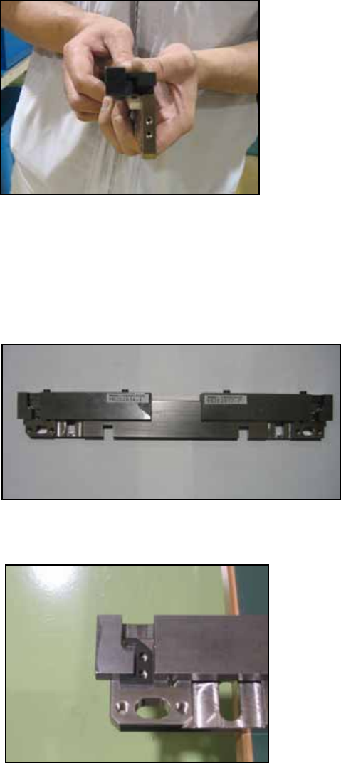
1.3 Board pass check sensor positioning bracket alignment
PM21030 & PM21040
1. Attach the jig as shown in the photo.
2. Mate the bracket undersurface with the jig undersurface and join them. M3×8 + M3
spring washer + special flat washer(W1041F)
NXT Repair Training Textbook
Conveyor Unit
FK-9F98-43-0E
Edition 1.0 6 / 46 FUJI Machine Mfg. Co., Ltd.
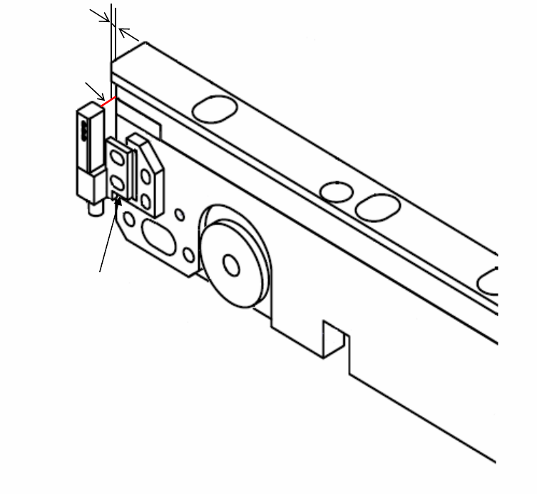
3. Glue the sensor to the surface of the aligned bracket and position it.
1mm
Sensor Beam
Glue this surface
to the bracket
NXT Repair Training Textbook
Conveyor Unit
FK-9F98-43-0E
Edition 1.0 7 / 46 FUJI Machine Mfg. Co., Ltd.
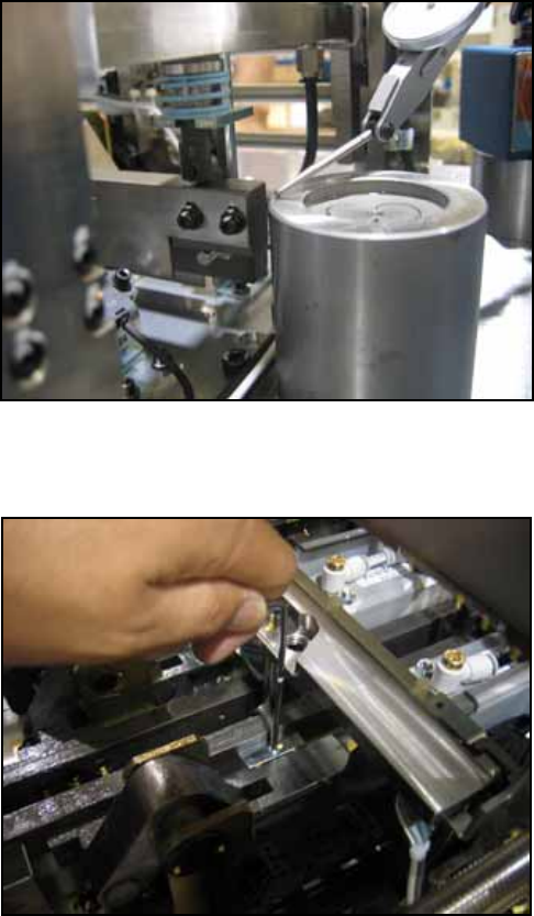
1.4 Conveyor up/down height adjustment (current M3 type)
Downward end type PM45780
Backup plate type PM47270
1. Remove the parts camera and check the installation surface for rust or unevenness
before placing the jig (PM45780) on the surface.
2. Remove the head and set the dummy head jig (AA18T00) in its place. Set a dial gage
stand on the dummy head jig and set the dial gage to 0 on the jig (PM45780). Unclamp
the conveyor.
3. The height of the rail that contacts the cam follower should be +/- 0.25mm in relation to
the jig. On the machine it is not possible to run the dial gage along the rail in one
motion, therefore change the position of the dial gage as necessary and measure to
the end of the rail.
4. If necessary use the hollow bolt to adjust the height of the rail.
Caution: at the front side there is a lock nut on the underside.
NXT Repair Training Textbook
Conveyor Unit
FK-9F98-43-0E
Edition 1.0 8 / 46 FUJI Machine Mfg. Co., Ltd.