1_NXT Conveyor(1.0)E.pdf - 第17页
C C h h a a p p t t e e r r 2 2 C C h h e e c c k k i i n n g g t t h h e e C C o o n n v v e e y y o o r r NXT Repair Training Textbook Conveyor Unit FK-9F98-43-0E Edition 1.0 16 / 46 FUJI Machine Mfg. Co., Ltd.
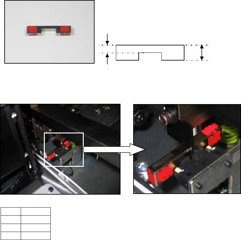
1.8 Lifter up/down sensor adjustment (previous type)
1. The following jig is necessary for the adjustment.
2. Raise the lifter.
3. Place the jig (1) on the sensor (2) as shown below:
4. Adjust the position of the sensor flag (3) so that it is touching the top of the jig as
shown in the photo above. Lock the installation bolts for the sensor flag.
5. Remove the jig and then lower the lifter.
6. Confirm that the sensor flag cuts the sensor beam when the lifter is lowered.
No. Item
1 Jig
2 Sensor
3 Flag
PM32170
3.6mm
8.6mm
2
1
3
NXT Repair Training Textbook
Conveyor Unit
FK-9F98-43-0E
Edition 1.0 15 / 46 FUJI Machine Mfg. Co., Ltd.

C
C
h
h
a
a
p
p
t
t
e
e
r
r
2
2
C
C
h
h
e
e
c
c
k
k
i
i
n
n
g
g
t
t
h
h
e
e
C
C
o
o
n
n
v
v
e
e
y
y
o
o
r
r
NXT Repair Training Textbook
Conveyor Unit
FK-9F98-43-0E
Edition 1.0 16 / 46 FUJI Machine Mfg. Co., Ltd.
Chapter 2 – Checking the Conveyor
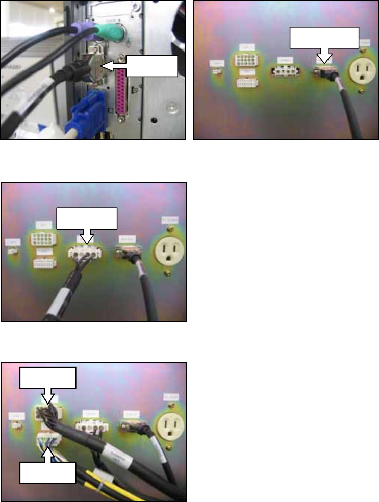
2.1 Connecting the conveyor to the conveyor inspection device
1. Connect the RS232C cable to the Com1 port on the computer and to the RS232C port
on the NXT Conveyor Inspection Device (hereafter referred to as CID).
2. Connect the power cable (POWER RH09900) to the CID.
3. Connect the CN1 (RH09910) and CN2 (RH09920) cables to the CID.
Com 1
RS232C
POWER
CN1
CN2
NXT Repair Training Textbook
Conveyor Unit
FK-9F98-43-0E
Edition 1.0 17 / 46 FUJI Machine Mfg. Co., Ltd.