1_NXT Conveyor(1.0)E.pdf - 第15页
4. Make sure that the back up plate is in place and then raise the lifter to clam p the 7.4mm thick part of the combination plate as shown: 5. Adjust the position of the sensor flag so that the sensor LED is just ON (the…
1.6 Board transport rail height adjustment
Z0 board top surface height measurement jig 203mm PM36290
1. Remove the reject parts box and place the jig. Set the dial gage to 0 on surface A.
Loosen and adjust the M5 x 10 bolt so that the surface with the reference rail removed
becomes 0. However, be aware that it is necessary to check the parallelism of the
reference rail if it is removed.
2. B is the same height as the Z0 height detection sensor installation surface.
3. C is the same height as a clamped board (203mm).
1.7 Lifter up/down sensor adjustment (current type)
1. Raise the lifter and loosen the installation bolts for the Lane 1 sensor flag.
2. Lower the lifter and set the lane 1 width to 100.5mm.
3. Place the combination plate jig (PM45770) in lane 1 with the 7.4mm sides parallel to
the conveyor rails.
Lane 1
Sensor
Lane 2
Sensor
Sensor
Flag
Sensor
Flag
NXT Repair Training Textbook
Conveyor Unit
FK-9F98-43-0E
Edition 1.0 13 / 46 FUJI Machine Mfg. Co., Ltd.
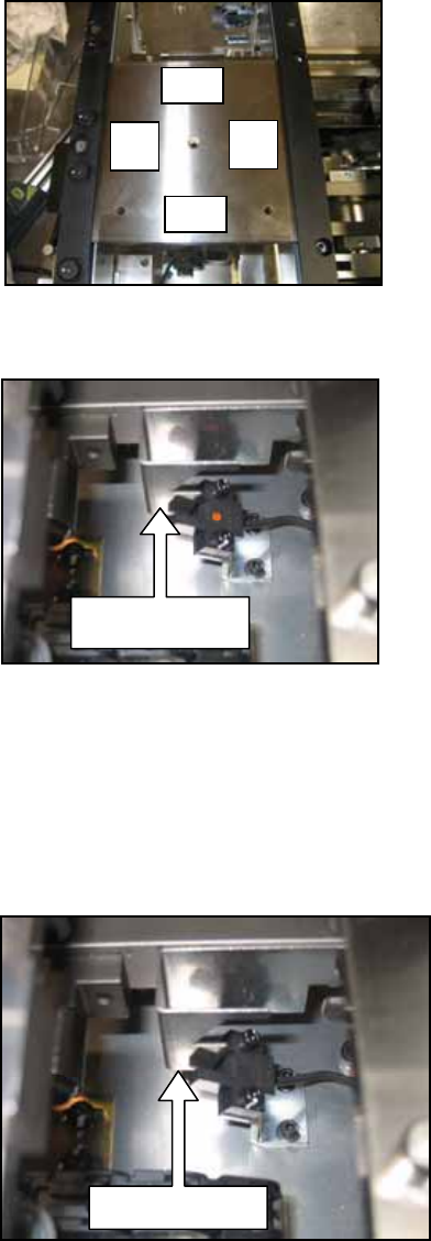
4. Make sure that the back up plate is in place and then raise the lifter to clamp the
7.4mm thick part of the combination plate as shown:
5. Adjust the position of the sensor flag so that the sensor LED is just ON (the bottom
edge of the sensor flag is just above the sensor beam).
6. Lower the lifter and change the position of the combination plate jig so that the 7.5mm
sides are parallel to the conveyor rails.
7. Make sure that the back up plate is in place and then raise the lifter to clamp the
7.5mm thick part of the combination plate.
8. Check that the sensor LED is OFF (the bottom edge of the sensor flag cuts the sensor
beam).
9. Lower the lifter and confirm that the sensor LED is OFF.
10. Repeat the procedure for the lane 2 sensor.
7.5
7.5
74
74
Sensor Fla
g
Sensor LED is ON when
the 7.4mm thick part of
the plate is clamped
Sensor Fla
g
Sensor LED is OFF when
the 7.5mm thick part of the
plate is clamped
NXT Repair Training Textbook
Conveyor Unit
FK-9F98-43-0E
Edition 1.0 14 / 46 FUJI Machine Mfg. Co., Ltd.
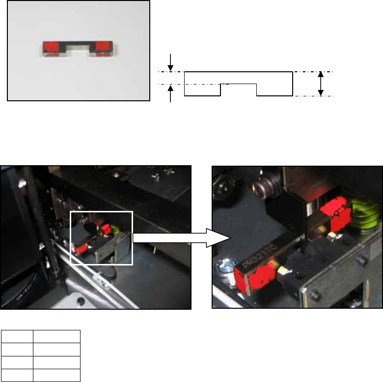
1.8 Lifter up/down sensor adjustment (previous type)
1. The following jig is necessary for the adjustment.
2. Raise the lifter.
3. Place the jig (1) on the sensor (2) as shown below:
4. Adjust the position of the sensor flag (3) so that it is touching the top of the jig as
shown in the photo above. Lock the installation bolts for the sensor flag.
5. Remove the jig and then lower the lifter.
6. Confirm that the sensor flag cuts the sensor beam when the lifter is lowered.
No. Item
1 Jig
2 Sensor
3 Flag
PM32170
3.6mm
8.6mm
2
1
3
NXT Repair Training Textbook
Conveyor Unit
FK-9F98-43-0E
Edition 1.0 15 / 46 FUJI Machine Mfg. Co., Ltd.