1_NXT Conveyor(1.0)E.pdf - 第35页
Checking the conveyor width change 1. Set the gap between each of the 4 convey or rails to approximately 130mm as shown below. 2. Click [Load] on the ConveyorTestTool and select SingleMotionChk_Wdth_20mm. 3. Click [Send1…
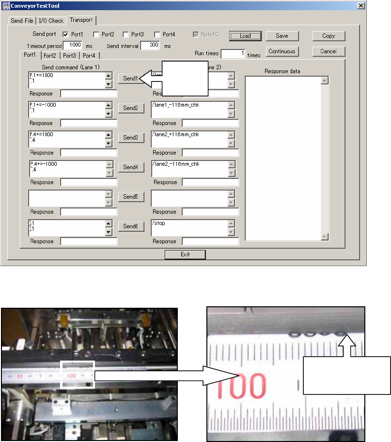
5. Click [Send1] in the ConveyorTestTool to move the conveyor 116mm from left to right.
6. Use the marking to check that the conveyor belt has moved 116mm from left to right.
7. Click [Send2] and confirm that the conveyor belt moves back to its original position
(116mm from right to left).
8. Repeat the procedure for lane 2 by clicking [Send 3] and then [Send 4].
Click
Send1
Check the
mark has
moved 116mm
NXT Repair Training Textbook
Conveyor Unit
FK-9F98-43-0E
Edition 1.0 33 / 46 FUJI Machine Mfg. Co., Ltd.
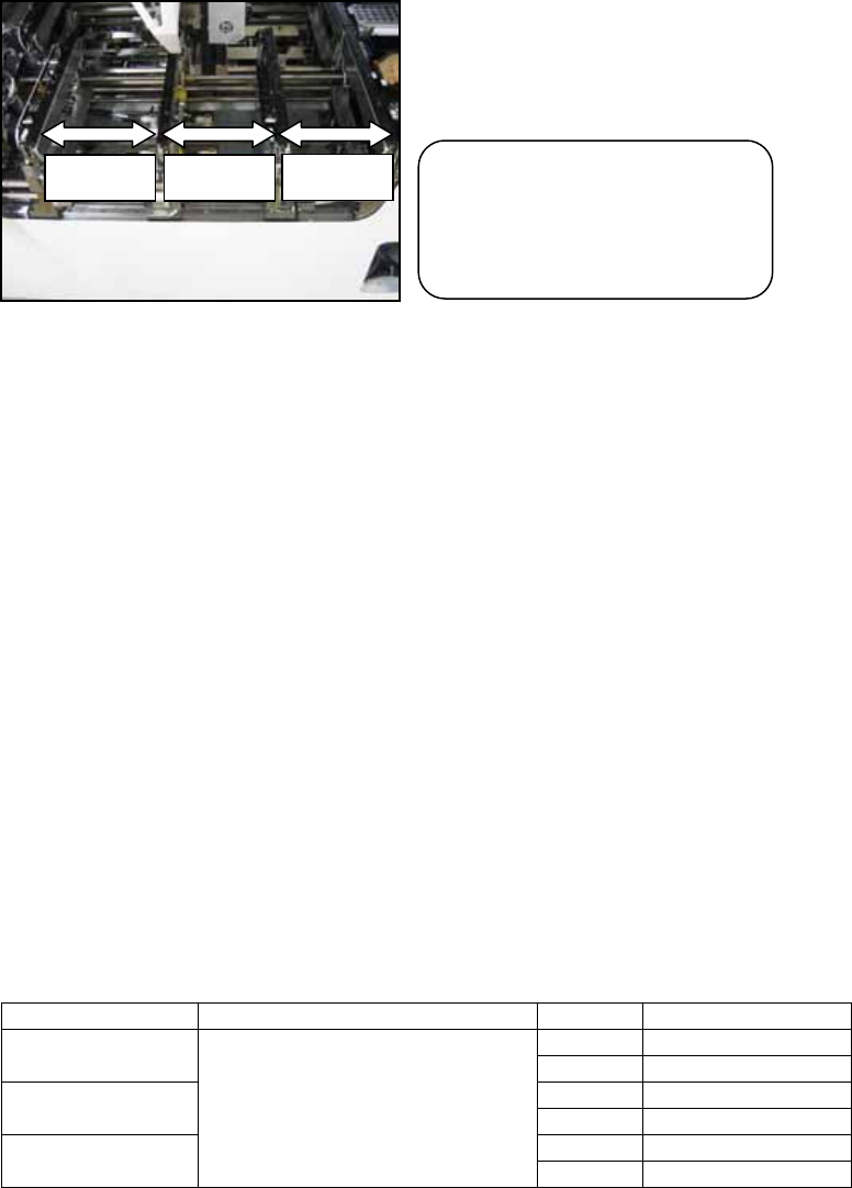
Checking the conveyor width change
1. Set the gap between each of the 4 conveyor rails to approximately 130mm as shown
below.
2. Click [Load] on the ConveyorTestTool and select SingleMotionChk_Wdth_20mm.
3. Click [Send1] and check that the lane1 adjustable rail moves 20mm towards the front
of the module.
4. Click [Send2] and check that the lane1 adjustable rail moves 20mm towards the rear of
the module.
5. Click [Send3] and check that the lane2 reference rail moves 20mm towards the front of
the module.
6. Click [Send4] and check that the lane2 reference rail moves 20mm towards the rear of
the module.
7. Click [Send5] and check that the lane2 adjustable rail moves 20mm towards the front
of the module.
8. Click [Send6] and check that the lane2 adjustable rail moves 20mm towards the rear of
the module.
9. Click [Load] and select SingleMotionChk_Wdth_40mm.
10. Repeat the procedure for the 40mm width change check.
Unit Command Send Width Change
Send1 20(40) mm to frontLn1 Adjustable
Rail Motor
Send2 20(40) mm to rear
Send3 20(40) mm to frontLn2 Reference
Rail Motor
Send4 20(40) mm to rear
Send5 20(40) mm to frontLn3 Adjustable
Rail Motor
SingleMotionChk_Wdth_20mm
SingleMotionChk_Wdth_40mm
Send6 20(40) mm to rear
Caution! Set the position of
each conveyor rail as shown.
Failure to do so could result
in a conveyor crash!
130mm
130mm
130mm
NXT Repair Training Textbook
Conveyor Unit
FK-9F98-43-0E
Edition 1.0 34 / 46 FUJI Machine Mfg. Co., Ltd.
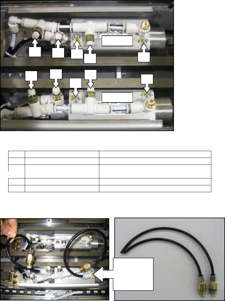
2.8 Adjusting the clamp/unclamp cylinder speed controllers (M3 double)
Stage 1 – slow-speed clamp/unclamp
1. Refer to the following photo of the clamp/unclamp cylinder speed controllers.
2. Set the volume of each of the lane1 speed controllers as shown in the table below.
3. Disconnect the air supply to the conveyor, and then attach the tube jigs to the lane1
speed controllers as shown in the following photo:
4. Reconnect the air supply to the conveyor.
5. Open the ConveyorTestTool and select the [Transport] tab.
6. Click [Load] and select [Ln1_LoSpeedClmp_chk].
No. M3 Speed Controllers Number of Turns from fully closed
1 Clamp (slow) 0.25
2 Unclamp (slow) 0.25
3 IN unclamp Fully open
4 Clamp (fast) Fully open
5 Unclamp (fast) Fully open
1
2
3
4
5
1
2
3
4
5
Lane1
Lane2
Attach the
tube jigs to
the speed
controllers
NXT Repair Training Textbook
Conveyor Unit
FK-9F98-43-0E
Edition 1.0 35 / 46 FUJI Machine Mfg. Co., Ltd.