1_NXT Conveyor(1.0)E.pdf - 第41页
11. Confirm that the response data reads M25, and then click [Cancel] to stop the conveyor operation. 12. Click [Load] – [LoadingTime_RvsStd_Ln2_chk] and repeat the procedure for lane2. 13. Set the width of both lanes to…
2. Open ConveyorTestTool and select the [I/O check] tab.
3. Turn CY004 and CY009 ON and then OFF to carry out the sensitivity adjustment for
the conveyor panel pass check sensors.
4. Select the [Transport] tab and click [Load] – [LoadingTime_M3PanelSizeChng].
5. Click [Send 5] to teach the conveyor that the board length is 50mm.
6. Click [Load] – [LoadingTime_RvsStd_Ln1_DoubleConv_chk].
7. Ensure that the lane1 conveyor is unclamped and that the backup plate or the block
jigs (PM24380) are in place.
8. Put the smallest panel (L50 x W50 x t0.4mm) in the center of lane1.
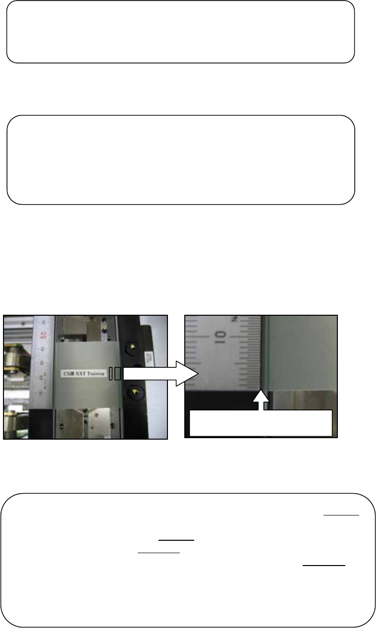
9. Place a scale on the conveyor rail and line it up with the edge of the panel.
10. Click [Continuous] and the panel is transported from the center to the end of the
conveyor, and then back to the center where it is clamped. Use the scale to check that
the panel always returns to the same position in the center of the conveyor.
Line up the edge of the scale
with the ed
g
e of the
p
anel
Note: if the panel travels to the center of the conveyor from the left end
of the conveyor it should stop in the same position the next time it
travels to the center from the left end
. If the panel travels to the center
of the conveyor from the right end
of the conveyor it should stop in the
same position the next time it travels to the center from the right end
.
The stopping position of the panel when it is traveling from the left end
may be slightly different to the stopping position when it is traveling
from the right end. This is normal. Only compare the stopping position
of the panel when it is traveling from the same end.
Note: if you turn OFF the CID power then you must teach the
conveyor the board length again. Turn ON the CID and load
the [LoadingTime_M3PanelSizeChng] command in the
ConveyorTestTool. Click [Send 5] to teach the conveyor that
the board length is 50mm.
Note: if you change the conveyor width at any time you must
carry out the sensitivity adjustment for the conveyor panel pass
check sensors again.
NXT Repair Training Textbook
Conveyor Unit
FK-9F98-43-0E
Edition 1.0 39 / 46 FUJI Machine Mfg. Co., Ltd.
11. Confirm that the response data reads M25, and then click [Cancel] to stop the
conveyor operation.
12. Click [Load] – [LoadingTime_RvsStd_Ln2_chk] and repeat the procedure for lane2.
13. Set the width of both lanes to 280mm.
14. Select the [I/O Check] tab and turn CY004 and CY009 ON and then OFF to carry out
the sensitivity adjustment for the conveyor panel pass check sensors.
15. Select the [Transport] tab and click [Load] – [LoadingTime_M3PanelSizeChng].
16. Click [Send 3] to teach the conveyor that the board length is 250mm.
17. Click [Load] – [LoadingTime_RvsStd_Ln1_DoubleConv_chk].
18. Ensure that the lane1 conveyor is unclamped and that the backup plate or the block
jigs (PM24380) are in place.
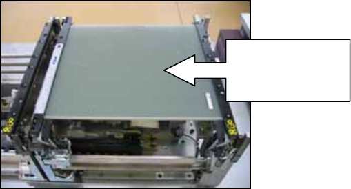
19. Put the medium panel (L250 x W280 x t6mm) in the center of lane1.
20. Place a scale on the conveyor rail and line it up with the edge of the panel.
21. Click [Continuous] and use the scale to check that the panel always returns to the
same position in the center of the conveyor.
22. Confirm that the response data reads M25, and then click [Cancel] to stop the
conveyor operation.
23. Click [Load] – [LoadingTime_RvsStd_Ln2_chk] and repeat the procedure for lane2.
24. Set the width of lane1 to 510mm.
25. Select the [I/O Check] tab and turn CY004 ON and then OFF to carry out the sensitivity
adjustment for the conveyor panel pass check sensors.
26. Click [Load] – [LoadingTime_RvsStd_Ln1_DoubleConv_chk].
Put the medium
panel in the
center of lane1
NXT Repair Training Textbook
Conveyor Unit
FK-9F98-43-0E
Edition 1.0 40 / 46 FUJI Machine Mfg. Co., Ltd.
27. Put the maximum panel (L250 x W510 x t6mm) in the center of lane1.
28. Place a scale on the conveyor rail and line it up with the edge of the panel.
29. Click [Continuous] and use the scale to check that the panel always returns to the
same position in the center of the conveyor.
30. Confirm that the response data reads M25, and then click [Cancel] to stop the
conveyor operation.
2.10 RS485 response check (checking communication between conveyors)
1. Startup the ConveyorTestTool and select the [Transport] tab.
2. Click [Load] and select [RS485comm_SingleConv_chk] or
[RS485comm_DoubleConv_chk] depending on the conveyor type.
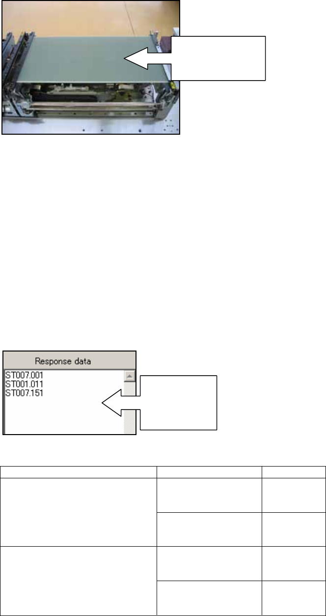
3. Click [Send1] and check the response in the “Response data” field.
4. Check that the response matches the response shown in the table below:
Send Command Device Type Response
M3 Single Conveyor ST007.001
ST001.011
ST007.151
RS485comm_SingleConv_chk
M6 Single Conveyor ST007.001
ST002.011
ST007.151
M3 Double Conveyor ST007.001
ST001.011
ST007.151
RS485comm_DoubleConv_chk
M6 Double Conveyor ST007.001
ST002.011
ST007.151
Put the maximum
panel in the
center of lane1
Check the
response
data in this
field
NXT Repair Training Textbook
Conveyor Unit
FK-9F98-43-0E
Edition 1.0 41 / 46 FUJI Machine Mfg. Co., Ltd.