1_NXT Conveyor(1.0)E.pdf - 第9页
1.4 Conveyor up/down height ad justment (current M3 ty pe) Downward end type PM45780 Backup plate type PM47270 1. Remove the parts camera and check the installation surface for rust or unevenness before placing the jig (…
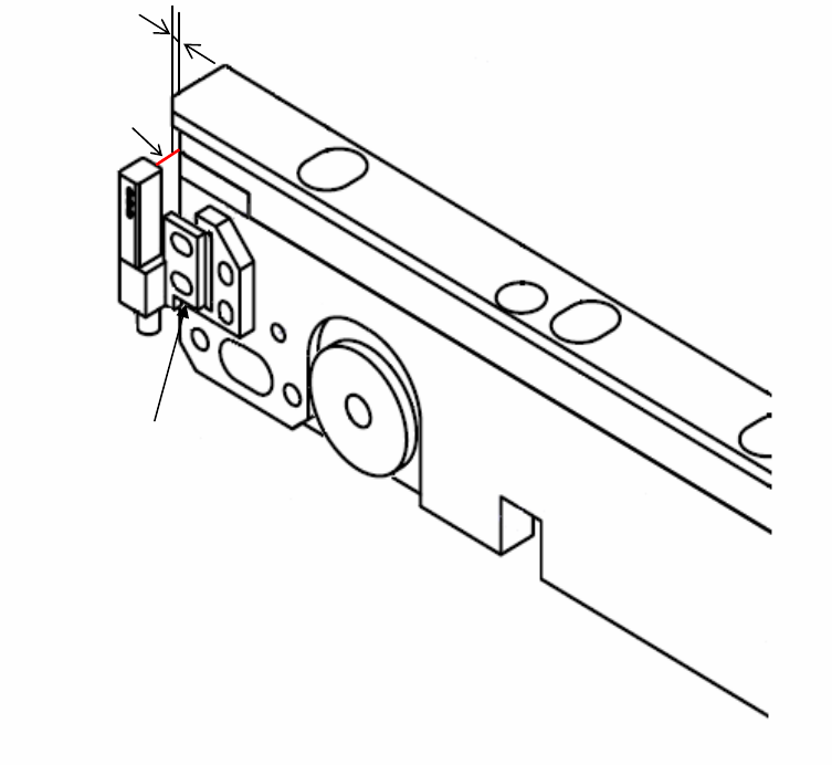
3. Glue the sensor to the surface of the aligned bracket and position it.
1mm
Sensor Beam
Glue this surface
to the bracket
NXT Repair Training Textbook
Conveyor Unit
FK-9F98-43-0E
Edition 1.0 7 / 46 FUJI Machine Mfg. Co., Ltd.
1.4 Conveyor up/down height adjustment (current M3 type)
Downward end type PM45780
Backup plate type PM47270
1. Remove the parts camera and check the installation surface for rust or unevenness
before placing the jig (PM45780) on the surface.
2. Remove the head and set the dummy head jig (AA18T00) in its place. Set a dial gage
stand on the dummy head jig and set the dial gage to 0 on the jig (PM45780). Unclamp
the conveyor.
3. The height of the rail that contacts the cam follower should be +/- 0.25mm in relation to
the jig. On the machine it is not possible to run the dial gage along the rail in one
motion, therefore change the position of the dial gage as necessary and measure to
the end of the rail.
4. If necessary use the hollow bolt to adjust the height of the rail.
Caution: at the front side there is a lock nut on the underside.
NXT Repair Training Textbook
Conveyor Unit
FK-9F98-43-0E
Edition 1.0 8 / 46 FUJI Machine Mfg. Co., Ltd.
・ Rear side
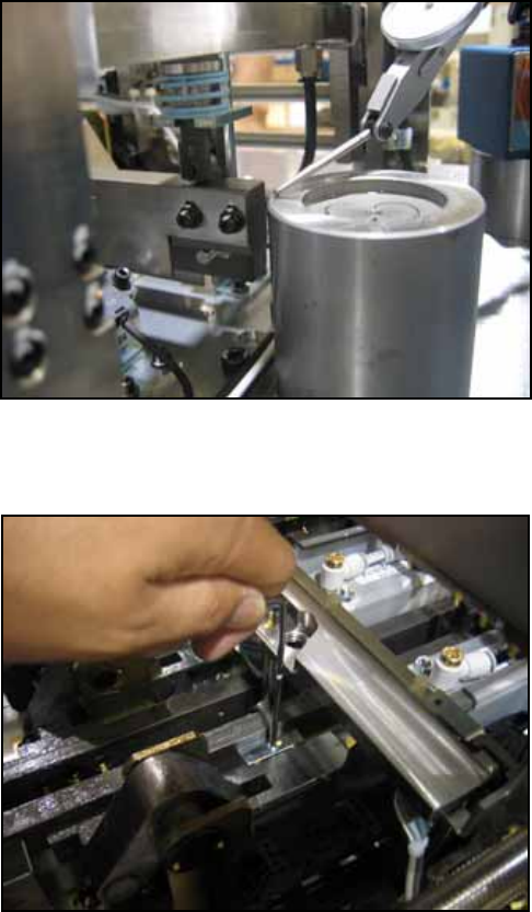
5. Clamper raised position measurement.
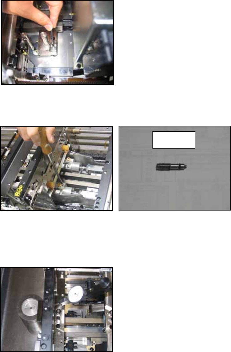
Cut the air supply to the machine. Remove the slow clamp speed controller as shown
in the photo below. Fully screw the jig (PZ14950) into the hole where the speed
controller was removed.
6. Supply the air and clamp the conveyor. (Stop at the middle position where clamp high
speed switches to low speed). Set the jig (PM47270) in the parts camera position and
set a dial gage to 0 on the jig.
7. Run the dial gage over the part where the back up plate sits and check that the total
difference in flatness is less than 0.05mm.
PZ14950
NXT Repair Training Textbook
Conveyor Unit
FK-9F98-43-0E
Edition 1.0 9 / 46 FUJI Machine Mfg. Co., Ltd.