1_NXT Conveyor(1.0)E.pdf - 第33页
2.7 Checking the conveyor motion Checking the conveyor transport 1. Select the [Transport] tab in the ConveyorTestTool and click [Load] 2. Select the file to load from the following path: Conveyor/CHK_Command_Cvtool/ CV_…
5. To check the operation of each sensor, block the beam and check that the status of
the I/O changes accordingly. Note that there is a short delay between blocking the
sensor on the conveyor and the change of status in the I/O check display.
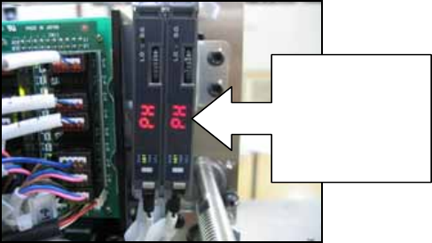
6. Confirm that when the sensor sensitivity adjustment output (CY004 and CY009) is ON
the amplifier displays “PH”. This sensitivity adjustment should be carried out whenever
the conveyor width is changed. To carry out the adjustment turn CY004 and/or CY009
ON and then OFF.
7. Use the list boxes on the output side of the I/O check window to turn each address ON
and OFF. Confirm that the corresponding actuators (etc) function normally.
8. Check that when the conveyor panel pass check L sensor (CX000 & CX008) comes
ON, the adjacent module stop trigger (CX002 & CX00A) for the same lane comes ON
simultaneously.
9. Turn ON the CY002 output and confirm that the green LED (front adjacent module stop
trigger) on the CID illuminates.
10. Turn ON the CY007 output and confirm that the red LED (rear adjacent module stop
trigger) on the CID illuminates.
11. Use the CY000 and CY001 outputs to clamp and unclamp the front conveyor and
check that the CX004 input turns ON and OFF.
12. Use the CY005 and CY006 outputs to clamp and unclamp the rear conveyor and
check that the CX00C input turns ON and OFF.
When CY004 &
CY009 are ON
the amplifiers
should display
“PH”
NXT Repair Training Textbook
Conveyor Unit
FK-9F98-43-0E
Edition 1.0 31 / 46 FUJI Machine Mfg. Co., Ltd.
2.7 Checking the conveyor motion
Checking the conveyor transport
1. Select the [Transport] tab in the ConveyorTestTool and click [Load]
2. Select the file to load from the following path: Conveyor/CHK_Command_Cvtool/
CV_Test_V83 (for old type conveyors) or CV_Test_V84 (for new type conveyors)
/SingleMotionChk_Transport.
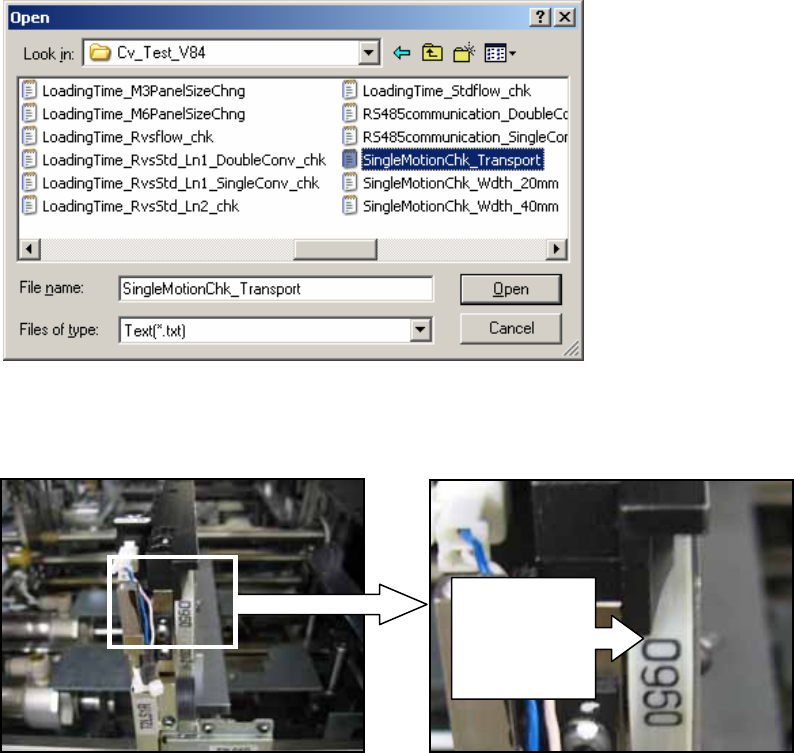
3. Push the emergency stop button on the CID, and manually set the lane 1 conveyor belt
so that one of the markings on the belt is lined up with the end of the conveyor as
shown below.
4. Release the emergency stop button on the CID.
Marking on
belt is lined
up with end
of conveyor
NXT Repair Training Textbook
Conveyor Unit
FK-9F98-43-0E
Edition 1.0 32 / 46 FUJI Machine Mfg. Co., Ltd.
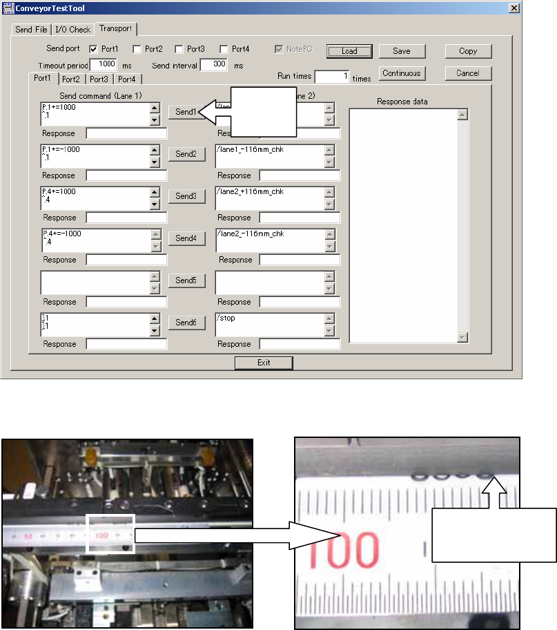
5. Click [Send1] in the ConveyorTestTool to move the conveyor 116mm from left to right.
6. Use the marking to check that the conveyor belt has moved 116mm from left to right.
7. Click [Send2] and confirm that the conveyor belt moves back to its original position
(116mm from right to left).
8. Repeat the procedure for lane 2 by clicking [Send 3] and then [Send 4].
Click
Send1
Check the
mark has
moved 116mm
NXT Repair Training Textbook
Conveyor Unit
FK-9F98-43-0E
Edition 1.0 33 / 46 FUJI Machine Mfg. Co., Ltd.