ACT - Accuracy Check Tool.pdf - 第213页
ACT with SSW 7xx / User Manual 07/2017 Edition 105 7 Troubleshooting 7.1 Update to SIPLACE Pro 11.x ff but no Upda te of the Stat ion Software to 707.1 SP1 HF2 ff With SIPLACE Pro 11.x ff and 707. 1 SP1 HF2 and the comp …
ACT with SSW 7xx / User Manual 07/2017 Edition
104
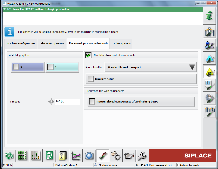
► Additionally, in the same view select in the Placement process (advanced) tab the Simulate
placement of components function.
Figure 6-19: Simulating placement of components
► Now load the black ALU plate into the machine and pay attention to the error-free transport and
clamping process.
ACT with SSW 7xx / User Manual 07/2017 Edition
105
7 Troubleshooting
7.1 Update to SIPLACE Pro 11.x ff but no Update of the Station
Software to 707.1 SP1 HF2 ff
With SIPLACE Pro 11.x ff and 707.1 SP1 HF2 and the compatible 706.2.SP1 HF2 version, all
heads with P&P functionality have been united into a new ACT placement program. For this with
ACT import 11.x in SIPLACE Pro, the SST 33 / 36 camera types and the 518 nozzle have been
removed from the CC02-05 and the CC02-05_CPP has been canceled.
Furthermore, the CC07-500 has been replaced by a CC02-05_FC.
If an update has been performed to SIPLACE Pro 11.x ff but no update of the station software to
707.1 SP1 HF2 ff, the corresponding components fail in the station software.
Recommended solution: Update to 707.1 SP1 HF2 (or higher)
Alternative solution: (if no software update can be installed)
► In this case, select the ACT_CC02-05_CPP_TH board in SIPLACE Pro. See Table 4-2.
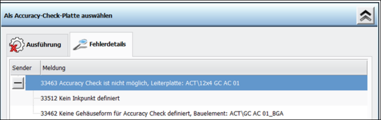
7.2 Specification of False Placement Programs
If other data is specified by SIPLACE Pro or changes on the ACT objects are performed in
SIPLACE Pro (directory names and object names of components), the following error messages
occur at the station.
ACT in station software 707.x
ACT with SSW 7xx / User Manual 07/2017 Edition
106
7.3 Measuring Errors
7.3.1 Several Components Cannot be Measured
The ACT measurement is performed with front-light.
I.e. the illumination of the board camera is used to illuminate the component on the plate.
To keep the contrast in the image constant, the so-called light plate (black protective plate) is used
at the bottom side of the ACT glass plate.
Possibly, this light plate was not inserted or it is scratched or dirty.
See section 4.2.3.
7.3.2 Dirty Components / Foil
In principle, the double-sided adhesive foil can be used several times until (too many) measuring
errors or runaway values occur.
"Runaway values" are often caused by dirt on the adhesive foil.
E.g.: crumbs, lint, hair, rubbed-off parts from the scraping equipment (e.g. board edges), locally
concentrated adhesive/scraps, etc.
These particles may interfere with the optical measurement of the fiducials or cause the
components to slip, tilt or rotate during placement, which must not be charged to the placement
process.
► Check the foil after each scraping with sufficient illumination from several angles.
If the number of error measurements exceeds a certain limit, the overall result is statistically
doubtful or an indication of another problem.
Until station software 707.x there is no output which features were not detected.
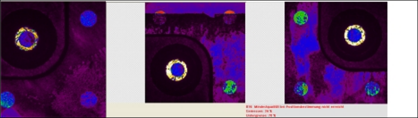
Examples of error measurements
From the video view at the station – up to 10 (part of) images of the buffer are visible:
In the second of 4 part images of a glass component (image in the middle) the upper two fiducials
are clearly covered by the used adhesive foil.
However, this error measurement will first be output with the last part image and is not integrated in
the calculations of the placement accuracy.