00195440-05-SG_D-Series_FSE-EN.pdf - 第123页
7 Axis Dynamics 7.3.4 Overview of Axis Unit 7.3 Axis Control Assemblies Student Guide SIPLACE D-Series (FSE) 123 7.3.4 7 . 3 . 4 O v e r v ie w o f A x is U n it Overview of Axis Unit 7.3.5 7 . 3 . 5 D / D i- S e r ie s …
7 Axis Dynamics
7.3 Axis Control Assemblies 7.3.3 Servo Amplifier TBS .. and SDS ...
122 Student Guide SIPLACE D-Series (FSE)
7.3.3
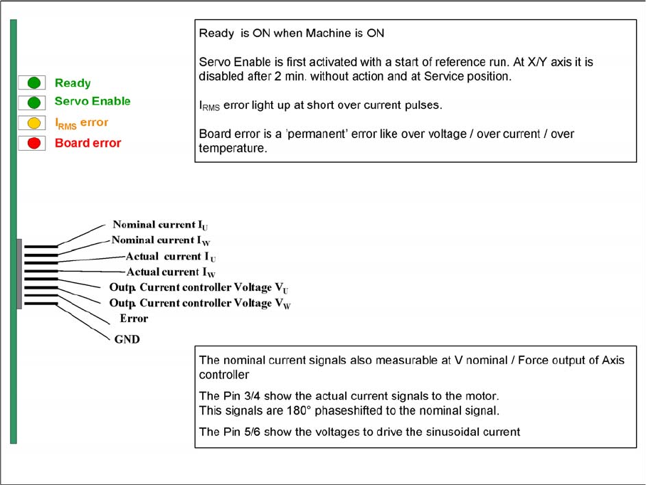
7.3.3 Servo Amplifier TBS .. and SDS ...
Servo Amplifier TBS .. and SDS ...
Servo amplifier
The servo amplifiers of type TBS are used for the X/Y and star axes, while the SDS servo amplifier is
used for the Z and DP axes. SDS servo amplifiers can process voltages of up to 60 VDC or 120 VDC,
depending on the input.
These SDS and TBS servo amplifiers can be reset with the servo release switch on the axis controller
board.
All servos have been set to the maximum motor current of the connected drive. This means that the ser-
vo amplifiers need to be used on an axis-specific basis.
Measuring point MP7:
In the event of errors, voltages can be measured at analog output MP7 with the help of the measuring
device, to help you ascertain the cause of the error.
▪ Overvoltage -1 V
▪ Overcurrent -2 V
▪ Overtemperature -3 V
▪ Nominal current exceeded -4 V
7 Axis Dynamics
7.3.4 Overview of Axis Unit 7.3 Axis Control Assemblies
Student Guide SIPLACE D-Series (FSE) 123
7.3.4
7.3.4 Overview of Axis Unit
Overview of Axis Unit
7.3.5
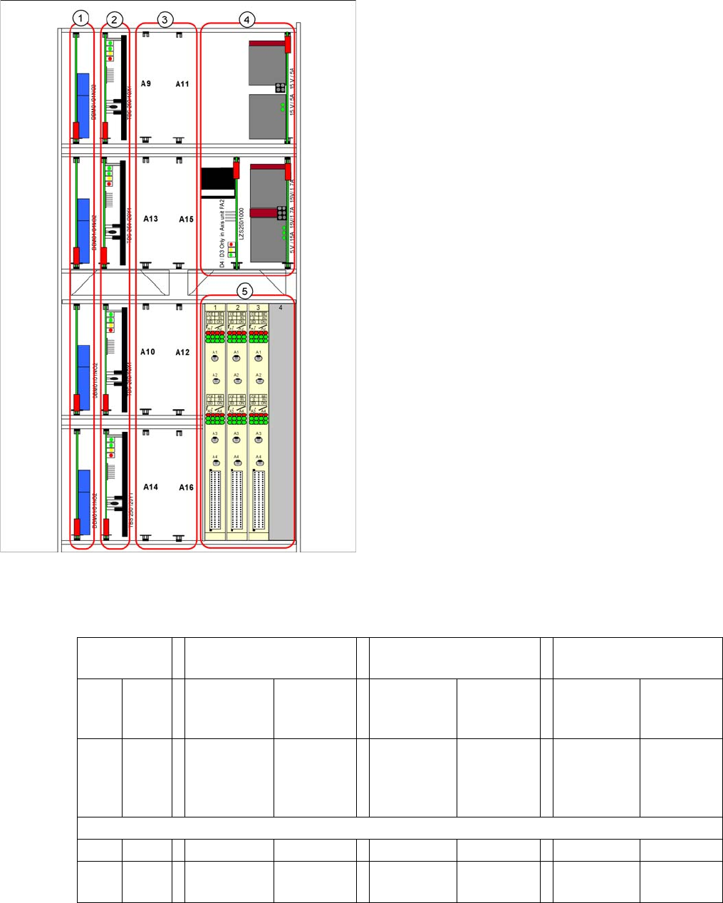
7.3.5 D/Di-Series Servo Positions
D/Di-Series Servo Positions
Servo positions for D1/D1i machine
Legend
1. Brake boards X/Y
2. Servo amplifier X/Y
3. Head servo positions
4. Power packs, ballast circuit (new power packs with
downwards compatibility)
5. Axis controller boards
Head servo
positions
C&P & P&P combination
at one D1/D1i gantry
/for D1/D1i single head
with C&P module
/for D1/D1i single head
with P&P module
A9 A11 SDS 60/1Z1
P&P mod-
ule.
SDS 60/
3Z1 C&P
module
--- SDS 60/
3Z1
SDS 60/1Z1
00353446-
04
---
A13 A15 SDS 60/
0.5D1 P&P
module
TBS 120/
3S1 C&P
module
--- TBS 120/
3S1
SDS 60/
0.5D1
00353447-
03
---
A10 A12 --- --- --- --- --- ---
A14 A16 SDS 60/1D1
C&P module
--- SDS 60/1D1 --- --- ---

7 Axis Dynamics
7.3 Axis Control Assemblies 7.3.6 Servo Card Positions for SIPLACE D3
124 Student Guide SIPLACE D-Series (FSE)
Servo positions for D2/D2i machine
7.3.6
7.3.6 Servo Card Positions for SIPLACE D3
Servo Card Positions for SIPLACE D3
PA1: D3 head servo cards for configuration of C&P6/12 or TWIN Head at gantry 1
PA1: D3 head servo cards for configuration of C&P6/12 or TWIN Head at gantry 4
Uneven axis
servo num-
bers for first
gantry(ies) of
PA
For C&P12 For C&P6 For TWIN (next genera-
tion)
Segment 2 Segment 1
A9 A11 TBS 120/
3S1
00353445-
04
SDS 60/
3Z1
03002141-
02
TBS 120/
3S1
00353445-
04
SDS 60/
3Z1
03002141-
02
SDS 60/1Z1
00353446-
04
SDS 60/
1Z1
00353446-
04
A13 A15 --- --- --- --- SDS 60/
0.5D1
00353447-
03
SDS 60/
0.5D1
00353447-
03
No DP servo in upper
area
No DP servo in upper
area
Even axis
servo num-
bers for sec-
ond
gantry(ies+)
of PA
For C&P12 For C&P6 For TWIN
Segment 2 Segment 1
A10 A12 TBS 120/
3S1
00353445-
04
SDS 60/
3Z1
03002141-
02
TBS 120/
3S1
00353445-
04
SDS 60/
3Z1
03002141-
02
SDS 60/1Z1
00353446-
04
SDS 60/
1Z1
00353446-
04
A14 A16 SDS 60/1D1
03002142-
02
SDS 60/
1D1
03002142-
02
SDS 60/1D1
03002142-
02
SDS 60/
1D1
03002142-
02
SDS 60/
0.5D1
00353447-
03
SDS 60/
0.5D1
00353447-
03
DP servo
Gantry 'n'
DP servo
gantry 'n+'
DP servo
Gantry 'n'
DP servo
gantry 'n+'
Gantry 1 C&P6/12 TWIN Head
A 9 Star axis Z2-axis
A 11 Z-axis Z1-axis
A 13 - DP2-axis
A 15 DP axis DP1-axis
Gantry 4 C&P6/12 TWIN Head
A 10 Star axis Z2-axis
A 12 Z-axis Z1-axis
A 14 Not connected DP2-axis
A 16 DP axis DP1-axis