00195440-05-SG_D-Series_FSE-EN.pdf - 第199页
11 Component Handling 11.1.3 Changeover Table 11.2 Setting the Height of the Changeove r Table Student Guide SIPLACE D-Series (FSE) 199 Overview: Changeover table stru cture (D1/D1i/D2/D2i shown a s ex ample) Legend 11.2…
11 Component Handling
11.1 Overview 11.1.3 Changeover Table
198 Student Guide SIPLACE D-Series (FSE)
11.1.3
11.1.3 Changeover Table
Changeover Table
Bulkcase feeder pneu-
matic supply
12 locations 15 locations
142335
15 locations
"Feeder claw" 12 locations 15 locations
Lifting/lowering device
(only function when
changeover table is
connected)
Yes No
(via front connec-
tor plug)
Yes Yes
Voltage supply for
Feeder Control Unit
(FCU)
8 VDC for control logic
30 VDC for feeder supply, including all linear feeders (24 VAC no longer need-
ed)
S feeder C&P12 bis 32 mm width bis 32 mm width
S feeder C&P6 bis 44 mm b width
S feeder P&P All up to 19 mm
component height
S feeder TWIN All up to 25 mm
component height
Assembly D4/D4i D3 D2/D2i D1/D1i
11 Component Handling
11.1.3 Changeover Table 11.2 Setting the Height of the Changeover Table
Student Guide SIPLACE D-Series (FSE) 199
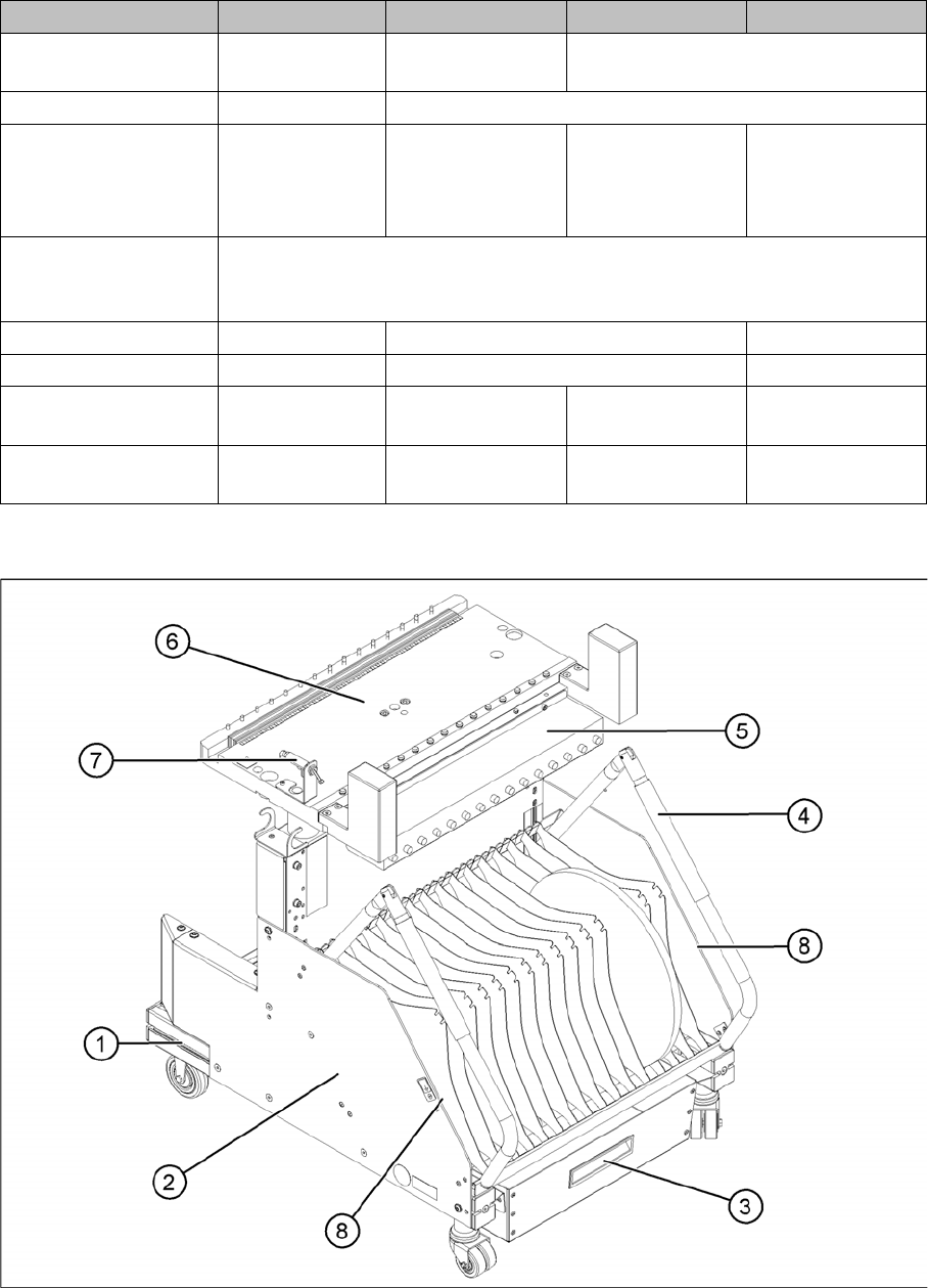
Overview: Changeover table structure (D1/D1i/D2/D2i shown as example)
Legend
11.2
11.2 Setting the Height of the Changeover Table
Setting the Height of the Changeover Table
The changeover table can be manually set to the following PCB transport heights
▪ 830 mm PCB transport height
▪ 900 mm PCB transport height
▪ 930 mm PCB transport height
▪ 950 mm PCB transport height
1 Moveable base with fixed and guide castor 5 Communication unit
2 Tape reels container 6 Table plate
3 Tape waste container 7 Switch for lowering the changeover table
4 Handle 8 Storage room for extra partition plates or
setup lists, next to the handles
11 Component Handling
11.2 Setting the Height of the Changeover Table 11.2.1 Adjusting the Component Trolley Height
200 Student Guide SIPLACE D-Series (FSE)
11.2.1
11.2.1 Adjusting the Component Trolley Height
Adjusting the Component Trolley Height
► Screw the eyebolt into the M12 hole provided (1) on the component trolley table.
► Hook the leverage device into the eyebolt (2).
► Tighten the rope of the leverage device.
► Loosen the 8 hexagon socket-head screws, M6x12 (4).
► Lift or lower the component trolley table to the required height. Make sure that the hole for the re-
quired height in the bridge (5) is level with the top hole in the vertical profile bar (3).
► Fasten the bridge (5) to the vertical profile bar (3) with the 8 hexagon socket-head screws M6x12 (4).
► Unscrew the eyebolt from the component trolley table.
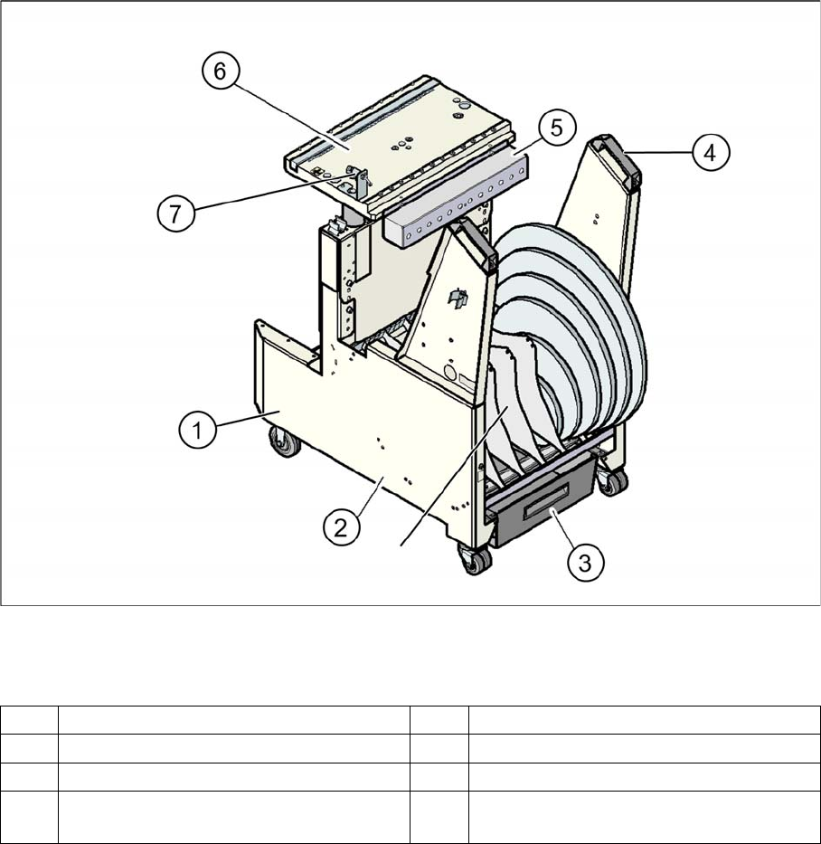
Changeover table (D4 shown as example)
Legend
1. Feeder table plate
2. Communication unit
3. Tape container
4. Waste container for tape cuttings
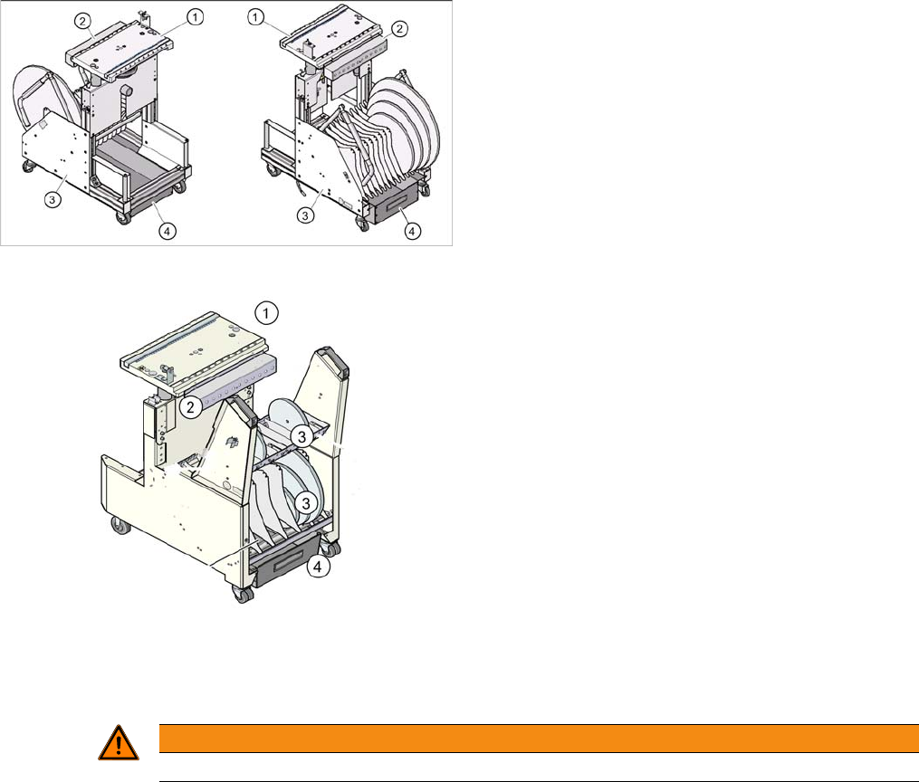
Changeover table (D4i shown as example)
1.
WARNING
Lift all feeder modules off the component trolley table plate.