00195440-05-SG_D-Series_FSE-EN.pdf - 第206页
11 Component Handling 11.4 Pneumatic Tape Cutter 11.4.1 Overview of Pneumatic Cutter w ith Empty Tape Duct 206 Student Guide SIPLACE D-Series (FSE) 11.4.1 1 1 . 4 . 1 O v e r v ie w o f P n e u m a t ic C u t t e r w it …

11 Component Handling
11.3.6 Additional Communication unit for splice detection 11.4 Pneumatic Tape Cutter
Student Guide SIPLACE D-Series (FSE) 205
11.3.6
11.3.6 Additional Communication unit for splice detection
Additional Communication unit for splice detection
11.3.7
11.3.7 Waffle Pack Changer (WPC)
Waffle Pack Changer (WPC)
To add a WPC4 in to a D1/D1i (D3: ab SR/MC 605) machine the following Steps are necessary:
► Remove COT Location 1BE-Tisch Stellplatz 1 (D3: Location 2)
► Remove the empty-tape duct assembly.
► Remove the waste slide.
► Remove the changeover table stopper.
► Fit the fixed changeover table WPC4 and screw tight.
► Assemble the empty tape canal
► Insert the WPC, lower and align.
11.4
11.4 Pneumatic Tape Cutter
Pneumatic Tape Cutter
Additional Communication unit for splice detection
An additional communication unit for the option Tracea-
bility with splice detection is necessary. The splice sen-
sors on the communication unit inform the station
software when a new component lot (reel) is spliced on.
This sets the new fill level for this component automatical-
ly.
Legend
1. The additional communication unit is screwed into
place, together with the changeover table communi-
cation unit.
NOTICE
Cause of Hazard
. Take care not to confuse the WPC4 title with the Station numbering single WPCs
NOTICE
Cause of Hazard
With D1/D1i-Machine the S-feeders are on the right side of WPC4
With D3-Machine S-Feeders are left of the WPC4.
NOTICE
Cause of Hazard
The D4/D4i machine is used as an example to describe the pneumatic cutter.
11 Component Handling
11.4 Pneumatic Tape Cutter 11.4.1 Overview of Pneumatic Cutter with Empty Tape Duct
206 Student Guide SIPLACE D-Series (FSE)
11.4.1
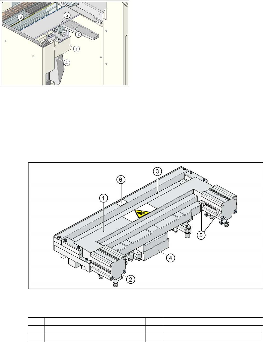
11.4.1 Overview of Pneumatic Cutter with Empty Tape Duct
Overview of Pneumatic Cutter with Empty Tape Duct
The pneumatic cutter is fixed to the machine frame with four screws and forms a unit with the empty tape
duct. It separates plastic, aluminum and paper tapes up to a maximum pocket depth of 25 mm. The tape
clippings fall down the waste slide, into the waste tape container of the component trolley.
The empty tape duct is designed to cover the cutting edges of the cutter (to avoid risk of injury), to guide
the empty component tapes to the cutter, to integrate the component reject container and accommodate
the C&P12 nozzle changer.
11.4.2
11.4.2 Structure and Function of the Pneumatic Tape Cutter
Structure and Function of the Pneumatic Tape Cutter
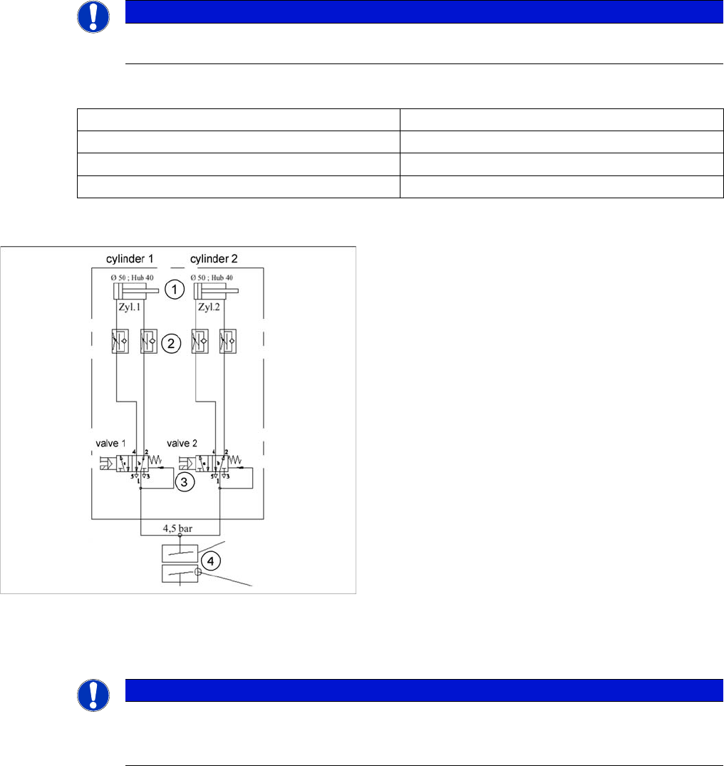
Pneumatic tape cutter
Legend
The empty tape duct guides the empty tapes through the opening (3) in the cutter.
Einzugsvorrichtung komplett (hier: D4/D4i)
Legend
1. Cross bar
2. Tape cutter
3. Empty Tape Duct
4. Waste slide
5. Proximity switch
1 Horizontal frame 4 Electronic control unit
2 Pneumatic cylinder 5 Proximity switch
3 Slot for empty tape 6 Fixed blade
11 Component Handling
11.4.3 Tape Cutter Control Unit 11.4 Pneumatic Tape Cutter
Student Guide SIPLACE D-Series (FSE) 207
The cutter is based on a horizontal frame (1) with a fixed cutting edge and a flexible blade, which is
moved by two short-stroke cylinders (2). At each forwards movement, the device cuts off the tape..
The proximity switch (5) signals the position of the short-stroke cylinder pistons and therefore of the cut-
ter blade. The control electronics (4) (under the cutter) register, for example, any components in the tape
which have not been cut. Cutting is only performed during the placement procedure. For operational
safety reasons, the tape cutter is integrated into the emergency stop circuit.
The tape cutter is activated when the gantry is moving to the placement position. Alternating one of the
cylinders start to front position. Once the first cylinder reaches the front position, the second cylinder is
started. Both signals ’blade in front position’ trigger control unit to withdraw both cylinders at the same
time.
11.4.2.1
11.4.2.1 Technical data
Technical data
11.4.2.2
11.4.2.2 Pneumatic Scheme Tape Cutter
Pneumatic Scheme Tape Cutter
11.4.3
11.4.3 Tape Cutter Control Unit
Tape Cutter Control Unit
NOTICE
The cutter can be removed within about 15 minutes for service purposes. For detailed informa-
tion about dismantling, refer to the service manual.
Compressed air supply 0.5 MPa = 5.0 bar
Compressed air consumption 135 l/min.
Cycle time 1.5 sec per cut
Supply voltages 5 VDC, 24 VDC
Compressed air supply to tape cutter
Legend
1. Drive cylinder for cutter blade movement 40 mm
stroke
2. Adjustable throttle valve on the pneumatic cylinder
3. 5/2 way magnetic valve
4. 4.5 bar compressed air supply and 24 V voltage sup-
ply via the PCC safety relay
Cutter only active when protective hoods are closed
NOTICE
Control unit [03006411-xx] is replaced by CAN node module.
This version of the control unit is replaced by the backwards compatible CAN node [03052027-
xx] module.