00195440-05-SG_D-Series_FSE-EN.pdf - 第31页
3 Overview 3.4.3 Axis Unit and Computer Unit 3.4 Assemblies Student Guide SIPLACE D-Series (FSE) 31 3.4.3 3 . 4 . 3 A x is U n it a n d C o m p u t e r U n it Axis Unit and Computer Unit Axis unit 1 – installation set on…
3 Overview
3.4 Assemblies 3.4.2 Sectors
30 Student Guide SIPLACE D-Series (FSE)
3.4.2
3.4.2 Sectors
Sectors
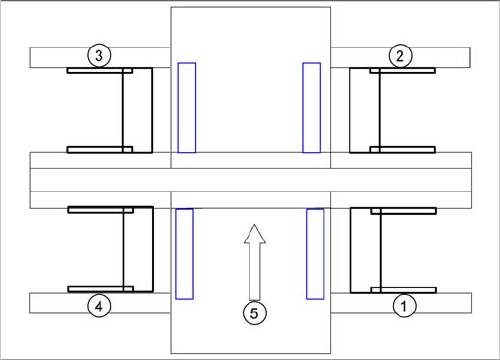
Sector 1:
▪ Transport control TSP 301
▪ CAN interface CAN Bus baudrate 500 KBit/s for S tables
▪ Assembly A3 CAN terminating resistor for S table location 1
▪ Vision DC/DC converter illumination digital camera gantry 1 - 4 (03002280-02)
▪ Terminal X100 power supply
▪ Pneumatic switch for changeover table 1
Sector 2:
▪ CAN I/O module 2 with CAN interface 500 KBit/s for S tables
▪ Assembly A3 CAN terminating resistor for S table location 2
▪ 3x fuse 24 V
▪ Relay K1 station – compressed air shutoff
▪ Terminal X200 power supply
▪ Pneumatic switch for changeover table 2
Sector 3:
▪ CAN interface CAN Bus baudrate 500 KBit/s for S tables
▪ Assembly A3 CAN terminating resistor for S table location 3
▪ Terminal X300 power supply
▪ Pneumatic switch for changeover table 1
Sector 4:
▪ CAN I/O module 2 with CAN interface 500 KBit/s for S tables
▪ Assembly A3 CAN terminating resistor for S table location 4
▪ 3x fuse 24 V
▪ Terminal X400 power supply
▪ Pneumatic switch for changeover table 1
SIPLACE D4 sectors
Legend
1. Sector 1
2. Sector 2
3. Sector 3
4. Sector 4
5. Transport direction
3 Overview
3.4.3 Axis Unit and Computer Unit 3.4 Assemblies
Student Guide SIPLACE D-Series (FSE) 31
3.4.3
3.4.3 Axis Unit and Computer Unit
Axis Unit and Computer Unit
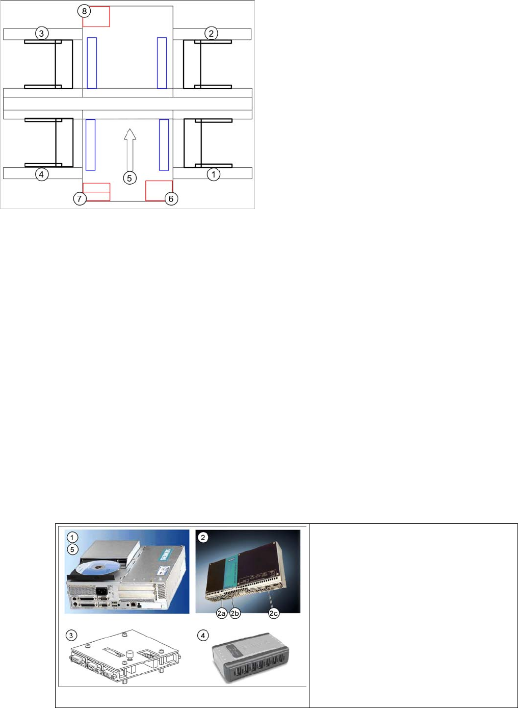
Axis unit 1 – installation set on the PCB input side:
▪ Servo board X, Y, star, Z, DP for PA1
▪ 3x Axis board A364
▪ 2x power supply 5 V/15 A, +/-15 V
Computer unit
▪ Box PC with CD-ROM drive (SR, SIPLACE Vision) or Single BoxPC (SR, SIPLACE Vision, MC)
▪ Micro Box PC (MC) or No Micro Box PC (MC) if system runs with Single BoxPC
▪ Multiplexer or Video Splitter if system runs with Single BoxPC
▪ USB hub
Axis unit 2 – installation set on the PCB output side:
▪ Servo board X, Y, star, Z, DP for PA2
▪ 3x Axis board A364
▪ 2x power supply 5 V/15 A, +/-15 V
▪ Ballast circuit
3.4.3.1
3.4.3.1 Computer Unit
Computer Unit
Axis unit and computer unit
Legend
1. Sector 1
2. Sector 2
3. Sector 3
4. Sector 4
5. Transport direction
6. Axis unit 1
7. Computer Unit
8. Axis unit 2
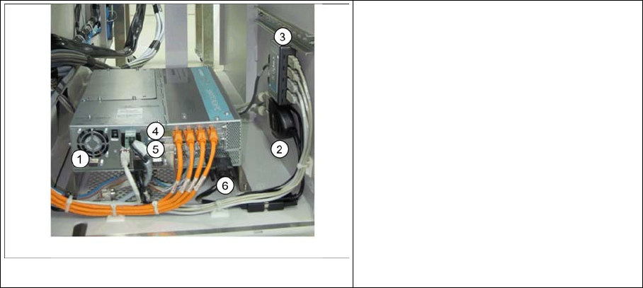
Computer unit D4
Legend
1. Station Computer SIPLACE BoxPC
2. Machine Controller SIPLACE Micro Box-
PC
3. Multiplexer
4. USB hub
5. USB CD-ROM drive
3 Overview
3.4 Assemblies 3.4.3 Axis Unit and Computer Unit
32 Student Guide SIPLACE D-Series (FSE)
1. Station Computer SIPLACE BoxPC (SR-SW, SIPLACE Vision-SW)
▪ 2x Hotlink boards for SIPLACE Vision, connected to the digital cameras
▪4x USB port
▪ 2x LAN Ethernet (LAN 1 connected to MC, LAN 2 hub or SIPLACE Pro)
▪ 1x VGA connection, connected to Multiplexer (monitor)
▪ Voltage supply 24 V DC
▪ The status display and the H1/H2 are active on the computer counterpart, while the BIOS is loaded.
2. Machine Controller SIPLACE Micro BoxPC (RMOS-SW)
▪ 2x LAN Ethernet (LAN 1 (2c) connected to SC, LAN 2 - not in use)
▪4x USB port
▪ 1x VGA connection, connected to Multiplexer (monitor)
▪ COM assembly – CAN 1 (2a) for PA1– CAN 2 (2b) for PA2
▪ Voltage supply 24 V DC
3. Multiplexer (switch over between SR and MC)
4. USB-Hub 2.0 – 4-Port (bzw. 7-Port) (anzuschliessen am USB-Port 0)
▪ Voltage supply connection
▪ USB input from station computer
▪ 4x (7x) USB outputs - 2x keyboard, 2x touchscreen (3x free)
5. External CD-ROM drive with USB interface (also for MC)
3.4.3.2
3.4.3.2 Computer Unit Di (Single BoxPC)
Computer Unit Di (Single BoxPC)
1. Station Computer SIPLACE Single BoxPC (SR-SW, MC-SW, SIPLACE Vision-SW)
▪ 1x Hotlink board (A24) for SIPLACE Vision, connected to the digital cameras
▪ 1x CAN BUS board – CAN 1 for PA1– CAN 2for PA2
▪4x USB port
▪ 2x LAN Ethernet (LAN 1 - not in use, LAN 2 hub for SIPLACE Pro)
▪ 1x DVI connection, connected to Video Splitter via DVI to VGA Cables (monitor)
▪ Voltage supply 24 V DC
▪ The status display and the H1/H2 are active on the computer counterpart, while the BIOS is loaded.
Computer unit Di
Legend
1. Station Computer SIPLACE Single Box-
PC
2. Video Splitter
3. USB hub
4. Hotlink Card (A24)
5. CAN BUS Card
6. DVI to VGA Cable