00195440-05-SG_D-Series_FSE-EN.pdf - 第42页
3 Overview 3.4 Assemblies 3.4.8 SIPLACE Vision 42 Student Guide SIPLACE D-Series (FSE) Technical data Technical data for camera type 34 Fiducial Criteria PCB fiducials Up to 3 (pa nels and clust er panels), Up to 6 for t…
3 Overview
3.4.8 SIPLACE Vision 3.4 Assemblies
Student Guide SIPLACE D-Series (FSE) 41
Star station 9:
▪ Pickup cycle
The nozzle is rotated into the "pickup" position.
▪ Placement cycle
The component is rotated into the correct placement angle with the help of the DP axis.
Between star station 11&12
▪ The "presence" and "height" of the component at the nozzle is checked by the component sensor
(optional).
3.4.8
3.4.8 SIPLACE Vision
SIPLACE Vision
For a diagram of the camera, details and technical background, refer to the chapter "Communication and
Control".
See also
16.6 SIPLACE Vision - Sensor Overview [ ➙ 279]
3.4.8.1
3.4.8.1 SIPLACE Vision - Sensor Overview
SIPLACE Vision - Sensor Overview
The digital SIPLACE Vision solution is another step towards the satisfaction of customer demands for
greater speed, flexibility and robustness.
Advantages of the digital Vision system:
▪ Robust and fast computing algorithms
▪ Flexible measurement processes
▪ Intuitive graphical user interface
▪ Geometric description of components at the machine
▪ State-of-the-art digital camera hardware
▪ Homogenous illumination of camera field of vision and components
Each C&P head has its own digital component camera.
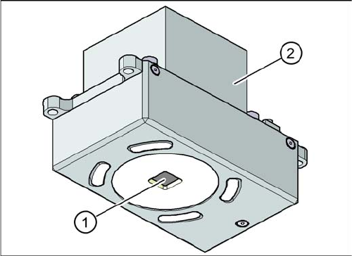
Digital PCB Camera (Type 34)
PCB camera under the gantry (X-axis)
Legend
1. PCB camera optics and illumination
2. Camera amplifier

3 Overview
3.4 Assemblies 3.4.8 SIPLACE Vision
42 Student Guide SIPLACE D-Series (FSE)
Technical data
Technical data for camera type 34
Fiducial Criteria
PCB fiducials Up to 3 (panels and cluster panels),
Up to 6 for the option "long board" (optional fiducials are issued by the
optimization process).
Local fiducials Up to 2 per PCB (can be of different types)
Library archive Up to 255 fiducial types per panel
Image processing Edge detection method (single feature) based on gray values
Method of illumination Front-lighting (3 levels, programable as required)
Erkennungszeit pro Marke/
Schlechtmarke
20 ms - 200 ms
Field of vision
5.78 x 5.78 mm
2
Distance from the focus plane 28 mm
Determine 2 fiducials X/Y position, angle of twist, central PCB displacement
Determine 3 fiducials Additional: shearing, displacement separately in X and Y direction
Fiducial shapes Synthetic fiducials: circle , cross , square , rectangle , diamond , circu-
lar, square and rectangular contours, doublecross
Pattern: any
Fiducial surface
Copper Without oxidation and soldering paste
Tin Warpage 1/10 of the structure width, with good contrast to surround-
ings
Dimensions of synthetic fiducials
Min. X/ Y size for circle and rectangle: 0.25 mm
Min. X/ Y size for square ring and rectangle frame: 0.3 mm
Min. X/ Y size for cross: 0.3 mm
Min. X/ Y size for doublecross: 0.5 mm
Min. X/ Y size for diamond: 0,35 mm
Min. frame width for square ring and rectangle frame: 0,1 mm
Min. bar width/bar spacing for cross, doublecross: 0,1 mm
Max. X/ Y size for all fiducial shapes: 3 mm
Max. bar width/bar spacing for cross, doublecross: 1,5 mm
Min. general tolerances: 2% of nominal dimensions
Max. general tolerances: 20% of nominal dimensions
Max. Winkeltoleranz: 2° für synthetische Marken
5° für Mustermarken
Dimensions of templates
Min. size 0.5 mm
Max. size 3 mm
Fiducial surroundings Space is not needed around the fiducials, provided there are no other
similar fiducial structures in the search field.
3 Overview
3.4.8 SIPLACE Vision 3.4 Assemblies
Student Guide SIPLACE D-Series (FSE) 43
Inkspot Criteria
Optional Digital Component Camera C&P12 (Type 38)
Technical data
Technical data for camera type 38
Methods ▪ Synthetic fiducial detection procedures
▪ Middle gray value
▪ Histogram method
▪ Template matching
Size of fiducial shapes or structures
Synthetic Fiducials For dimensions of synthetic fiducials, see "3.4.8.1.1.2 Fiducial Criteria"
[➙42].
Other methods Min. 0,3 mm
max. 3 mm
Cover material Covers well
Recognition time Depending on method, 20 ms - 0.2 s
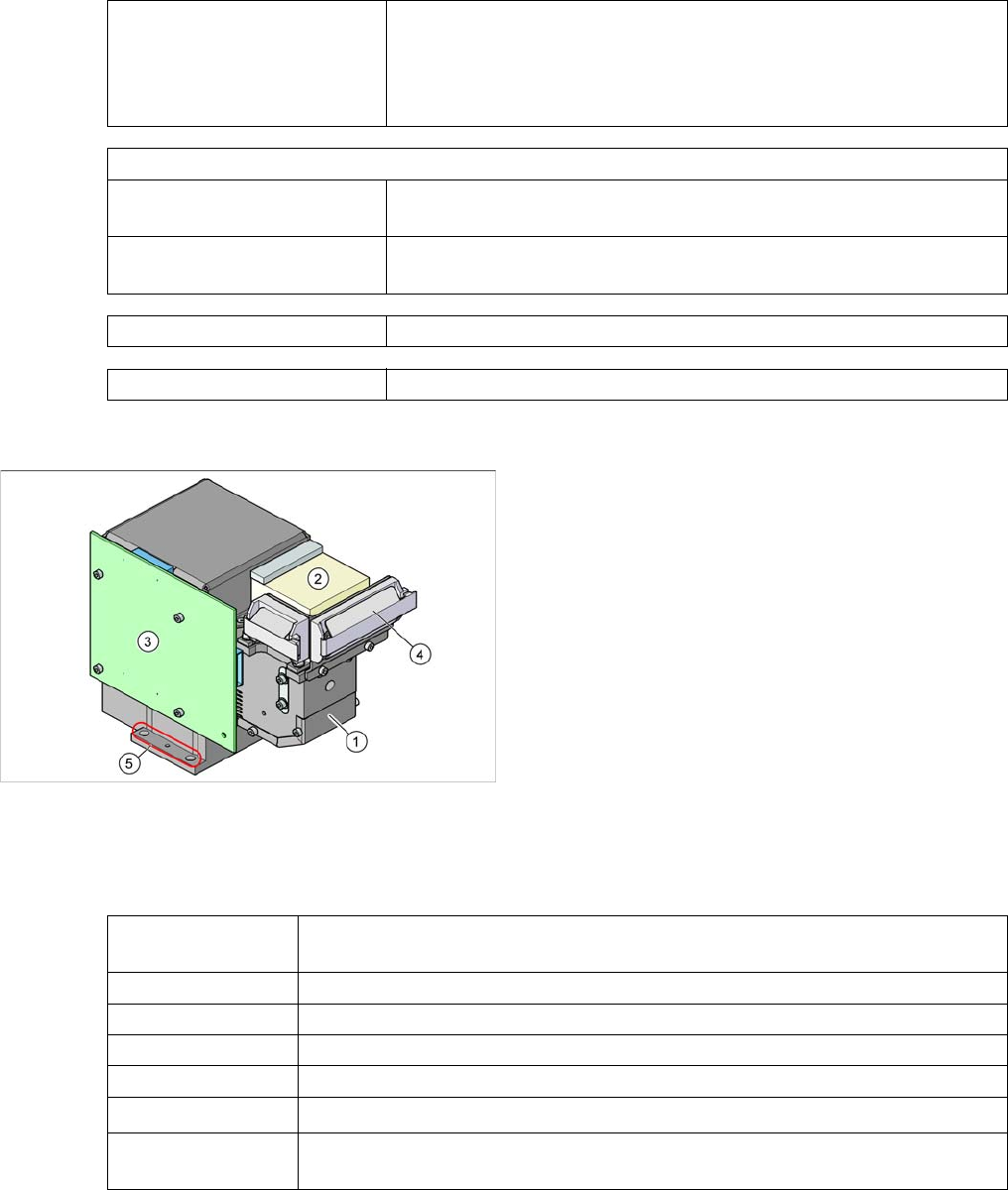
Component camera as option on the C&P12 head
Legend
1. Component camera optics and illumination
2. Camera amplifier
3. Illumination control
4. Flat ribbon cable holder for C&P head leads
5. Camera fixtures
2 x fixture drillings and 1 x centering drilling each on
both sides
The camera type 38 can be recognized by its type label.
Component dimen-
sions
0.2 x 0.1 mm
2
to 16 x 16 mm
2
Component range 0.2 x 0.1 mm² (01005) to PLCC36 (32R)
Min. lead pitch 0,1 mm
Min. ball pitch 0.25 mm
Min. ball diameter 0.14 mm
Field of vision
20.5 x 20.5 mm
2
Method of illumina-
tion
Front lighting (6 programmable options on 4 levels )