00195440-05-SG_D-Series_FSE-EN.pdf - 第17页
2 Operational Safety 2.4.1 Switches and Buttons on the Placement Machine 2.4 Safety E quipment Student Guide SIPLACE D-Series (FSE) 17 2.4 2 . 4 S a f e t y E q u ip m e n t Safety Equipment 2.4.1 2 . 4 . 1 S w it c h e …
2 Operational Safety
2.3 Safety Instructions for Moving the Component Trolley 2.3.1 Position of Controls for Docking and Undocking the Component Trolley
16 Student Guide SIPLACE D-Series (FSE)
► Connect the trolley with the plug provided before inserting it into the machine. Lift the trolley and
move it into the machine.
► In the machine, the pneumatic switch must always be down, to ensure that the table is not stopped
in an intermediate position.
2.3.1
2.3.1 Position of Controls for Docking and Undocking the Component Trolley
Position of Controls for Docking and Undocking the Component Trolley
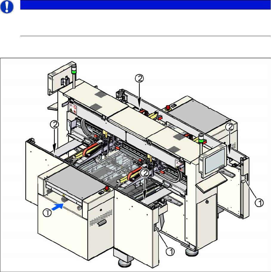
Position of pushbuttons on the component trolley
Legend
1. Connection for component trolley
2. Pushbutton for raising the changeover tables, with feeder cover plate flap above
▪ T = PCB direction of transport
The switch used to lower the changeover tables is located at the left, rear of the changeover table. This
switch will only be accessible when the feeder cover plate is open.
NOTICE
Optional equipment
Changeover tables in the D4/D4i/D2/D2i/D1/D1i series can be equipped with an optional device
to prevent the table being raised or lowered if it is not connected to the machine.
2 Operational Safety
2.4.1 Switches and Buttons on the Placement Machine 2.4 Safety Equipment
Student Guide SIPLACE D-Series (FSE) 17
2.4
2.4 Safety Equipment
Safety Equipment
2.4.1
2.4.1 Switches and Buttons on the Placement Machine
Switches and Buttons on the Placement Machine
2.4.1.1
2.4.1.1 Position of Switches and Buttons on the Placement Machine
Position of Switches and Buttons on the Placement Machine
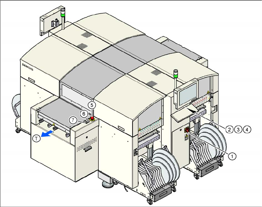
Position of switches and buttons - View of the PCB output side (D4)
2 Operational Safety
2.4 Safety Equipment 2.4.1 Switches and Buttons on the Placement Machine
18 Student Guide SIPLACE D-Series (FSE)
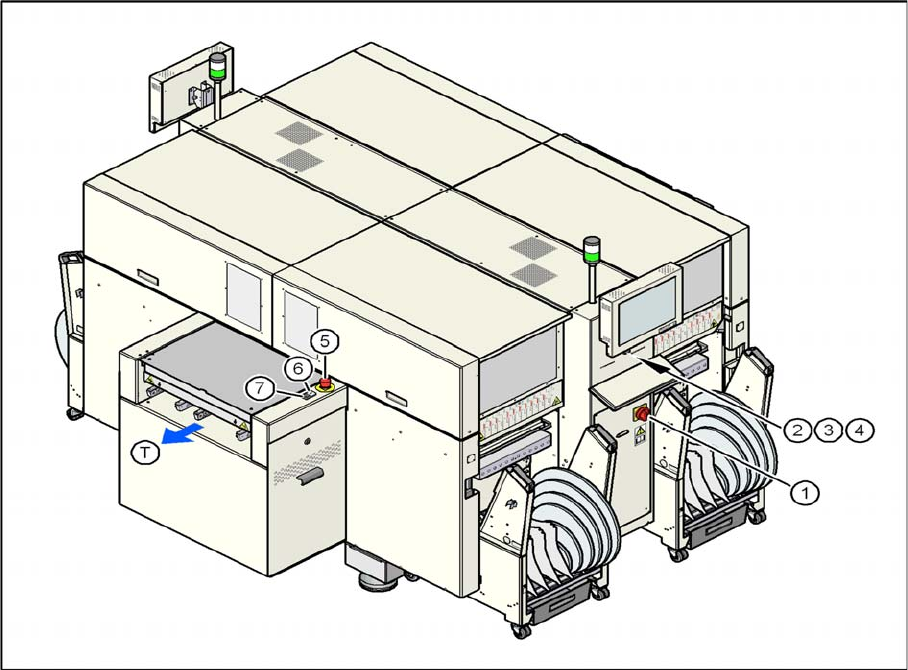
Position of switches and buttons – View of the PCB output side (D4i)
Legend
1. Main switch
2. Stop button (black) on the operator panel on the power supply side
3. Start button (white) on the operator panel on the power supply side
4. Component counter on the operator panel on the power supply side
5. Emergency stop button on the output side
6. Start button (white) on the output side
7. Stop button (white) on the output side
T = PCB direction of transport