00195440-05-SG_D-Series_FSE-EN.pdf - 第145页
9 C&P Placement Heads 9.1.1 Technical Data C&P12 9.1 Overview Student Guide SIPLACE D-Series (FSE) 145 9 9 C & P P la c e m e n t H e a d s C&P Placement Heads 9.1 9 . 1 O v e r v ie w Overview 9.1.1 9 . …
8 Gantry
8.5 Room for Your Sketches and Notes 8.4.2 Gantry Settings
144 Student Guide SIPLACE D-Series (FSE)
9 C&P Placement Heads
9.1.1 Technical Data C&P12 9.1 Overview
Student Guide SIPLACE D-Series (FSE) 145
9
9 C&P Placement Heads
C&P Placement Heads
9.1
9.1 Overview
Overview
9.1.1
9.1.1 Technical Data C&P12
Technical Data C&P12
Technical data C&P12
NOTICE
Cause of Hazard
The SIPLACE D1/D1i/D2/D2i/D3 machines with the optional Head Modularity function have
C&P12 and/or C&P6 placement heads.
D1/D1i machines also have a P&P head, in addition to the C&P head.
The SIPLACE D4/D4i machines have a C&P12 place-
ment head on each gantry. All other D/Di machines per-
mit the use of both C&P6 and C&P12 heads, with the
Head Modularity function.
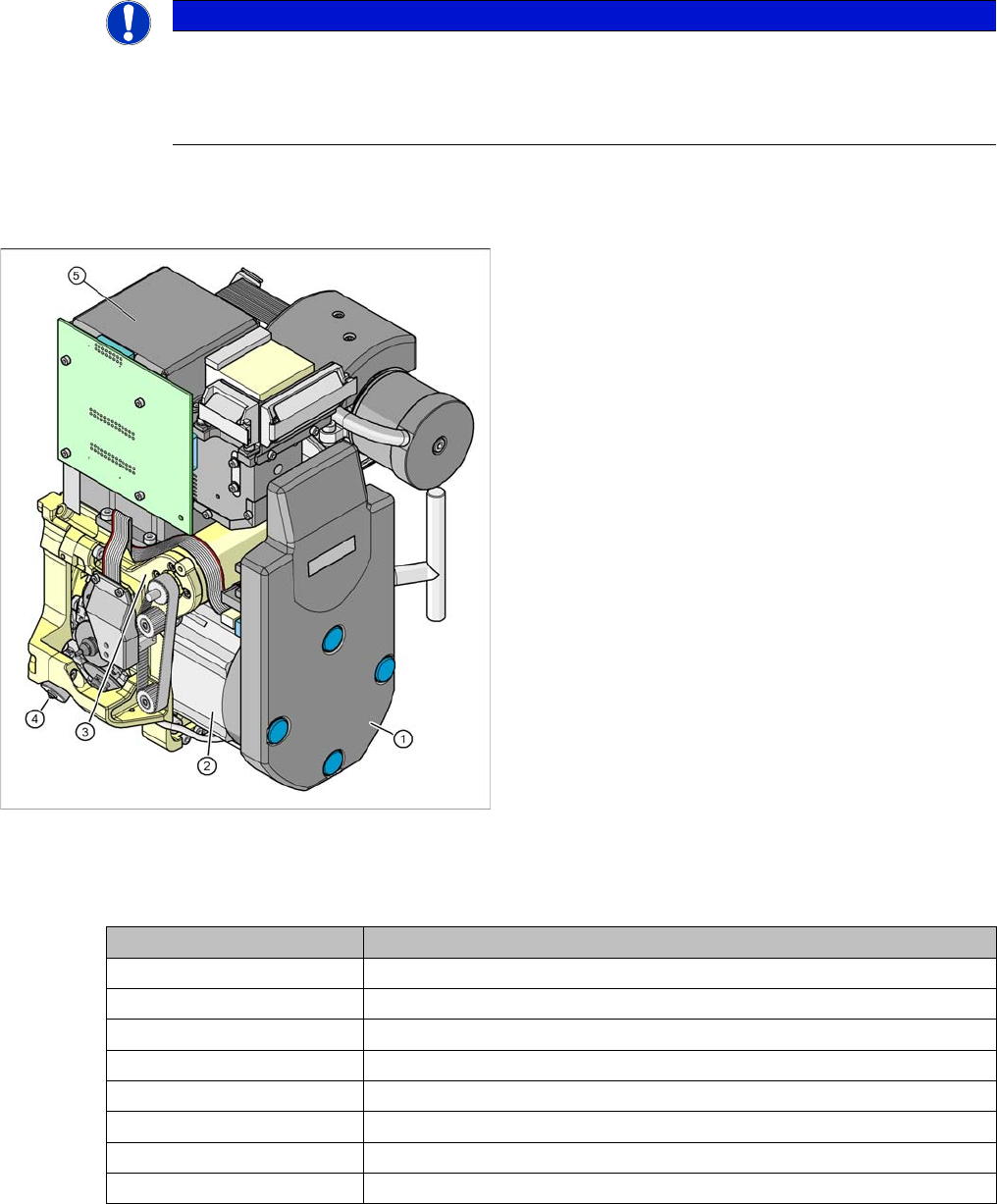
Legend
1. Intermediate distribution board (under the cover)
2. Star drive
3. Z drive
4. Valve positioning drive
5. Component camera C&P, type 28 (18x18) digital or
type 29 (27x27) digital, high resolution component
camera 18x18 or,optionally, SST29 for 0201
(0.5x0.25 mm) or SST38 from SW 604. or SST30
from SW 605.03SP2
Description 12 segment DLM 3
Component size 1 mm x 0.5 mm (0402)/0.5 mm x 0.25 mm (0201) to 18.7 mm x 18.7 mm
Component height 6.0 mm
Component weight 2.0 g
Placement accuracy +/- 80 µm at 4 (Sigma)
Angular accuracy +/- 0.7° at 4 (Sigma)
Placement force 2.4 - 5.0 N
Nozzle spectrum 901, 904, 905; 911-919; 920-925; 931-937
Nozzle changer Can be set up per magazine or garage
9 C&P Placement Heads
9.1 Overview 9.1.2 Camera Modularity on C&P 12 Head
146 Student Guide SIPLACE D-Series (FSE)
9.1.2
9.1.2 Camera Modularity on C&P 12 Head
Camera Modularity on C&P 12 Head
Technical data - component cameras
9.1.3
9.1.3 Overview of C&P6/12 Head Parts
Overview of C&P6/12 Head Parts
NOTICE
Cause of Hazard
The standard camera on the C&P12 is the 28.sst, although the component camera 29.sst, with
a higher resolution (for small 0201 components), can be installed as an option (the same max-
imum component dimensions apply in this case)
Smaller maximum component dimension apply when using the SST38 camera option. For fur-
ther settings and data for the C&P12 head, see the specifications for the relevant option.
For Di-series (for small 0201 and 01005 components), component camera 30 sst will replace
component camera 29 sst and 38 sst respectively.
Description 12 segment standard
SST 28
12 segment with SST 29 12 segment with SST 30
Component size:
Flip Chip/Bare Die
0.3mm x 0.3 mm (0201) to 18.7 mm x 18.7 mm 0.18mm x 0.18mm
(01005) to 27mm x
27mm
Component height 0.15 mm up to 6 mm 0.15 mm up to 6 mm 0.15 mm up to 6 mm
Placement accura-
cy
+/- 80 µm at 4 (Sigma) +/- 55 µm at 4 (Sigma)
Angular accuracy +/- 0.7° at 4 (Sigma) +/- 0.7° at 4 (Sigma)
Resolution of com-
ponent camera
50µm/pixels 26µm/pixels 17µm/pixels
C&P12 head
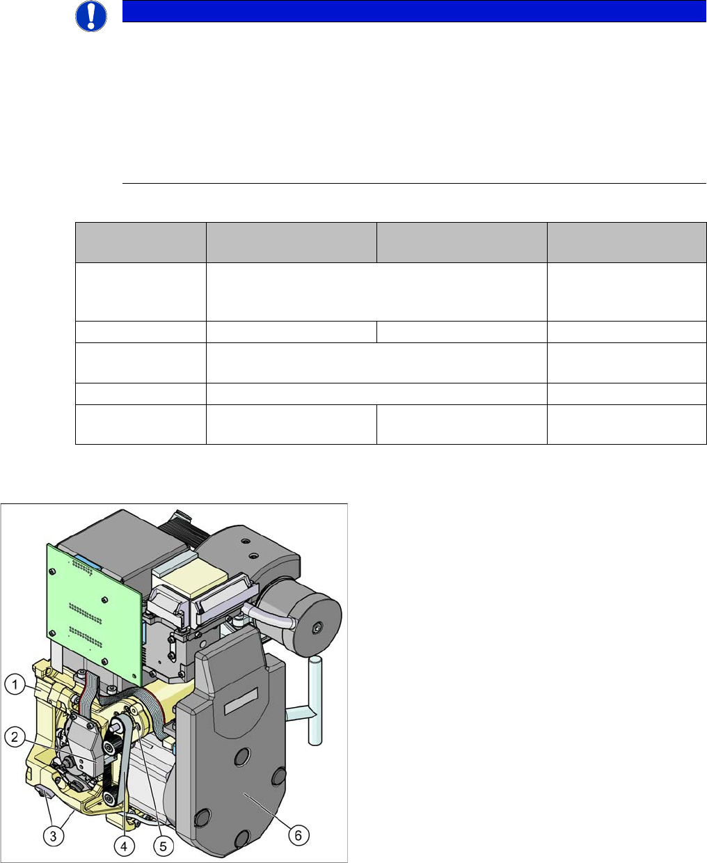
Legend - overview of parts 1
1. Collect&Place head 12 (DLM3)
[03041228-xx] (shown)
Collect&Place head 6 (DLM3)
[03048341-xx] (not for D4/D4i)
2. Light barrier "Z axis up " (behind the cover)
[00347297-xx]
3. Placement circuit valve positioning drive
[00368076-xx]
Reject circuit valve positioning drive
[00368074-xx]
4. Z axis toothed belt
[00334936-xx]
5. Z axis drive
[03038908-xx]
6. Intermediate distributor, digital (behind the cover)
[00330648-xx]