00195440-05-SG_D-Series_FSE-EN.pdf - 第40页
3 Overview 3.4 Assemblies 3.4.7 C&P12 Head DLM3 40 Student Guide SIPLACE D-Series (FSE) Legend Option: Digital camera SST.29 for the C&P12 head and compone nt sensor [0011 8021-xx] for 0201 placement. Note: Digit…
3 Overview
3.4.7 C&P12 Head DLM3 3.4 Assemblies
Student Guide SIPLACE D-Series (FSE) 39
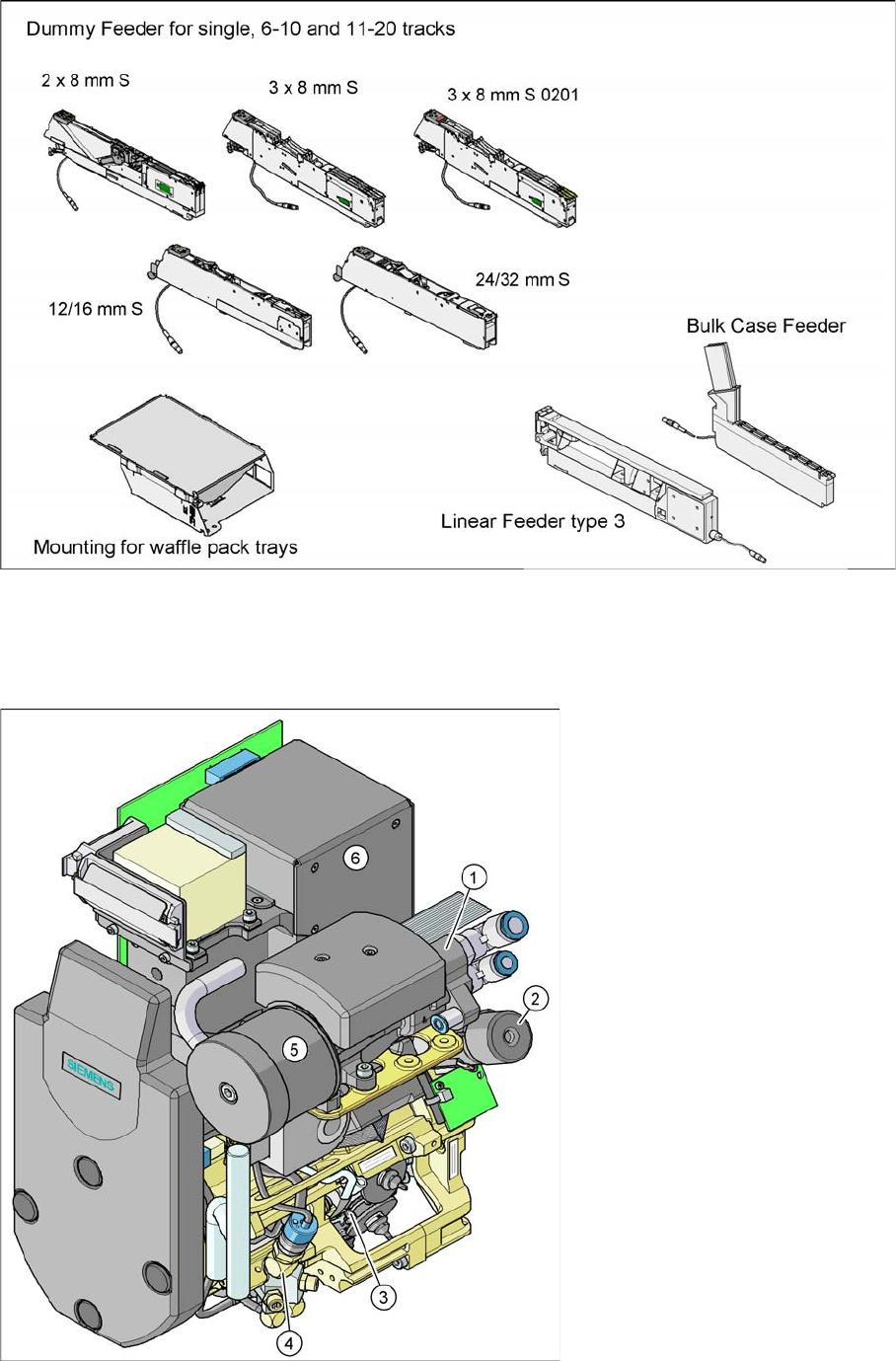
Overview of standard feeders
3.4.7
3.4.7 C&P12 Head DLM3
C&P12 Head DLM3
3.4.7.1
3.4.7.1 General
General
C&P12 Head DLM3
3 Overview
3.4 Assemblies 3.4.7 C&P12 Head DLM3
40 Student Guide SIPLACE D-Series (FSE)
Legend
Option: Digital camera SST.29 for the C&P12 head and component sensor [00118021-xx] for 0201
placement.
Note: Digital camera SST30 will replace SST29 in C&P12 head for D4i and SST29 in C&P6 head for
D1i/D2i
3.4.7.2
3.4.7.2 Overview of Functions for Star Stations 1-12
Overview of Functions for Star Stations 1 - 12
3.4.7.3
3.4.7.3 Position and Function of the Individual Star Stations
Position and Function of the Individual Star Stations
Star station 1:
▪ Pickup cycle
The nozzle is lowered towards the component. After a vacuum has been produced with the help of
the valve positioning function, the nozzle takes the component from the feeder module.
▪ Placement cycle
The nozzle, together with the component, is lowered onto the PCB that has been moved into place.
The valve is positioned to cut off the supply of vacuum to the nozzle. A brief burst of air separates
the component from the nozzle and the component is placed onto the board.
Star station 3:
▪ Abwurfzyklus bei D4/D4i/D3/D2/D2i
(Bei D1/D1i wird in Sternstation 1 in den P&P-Abwurfbehälter abgeworfen)
The valve is positioned to cut off the supply of vacuum to the nozzle. Defective components are re-
jected from the nozzle with a short air blast of compressed air and are discarded.
Star station 7:
▪ The component is optically centered.
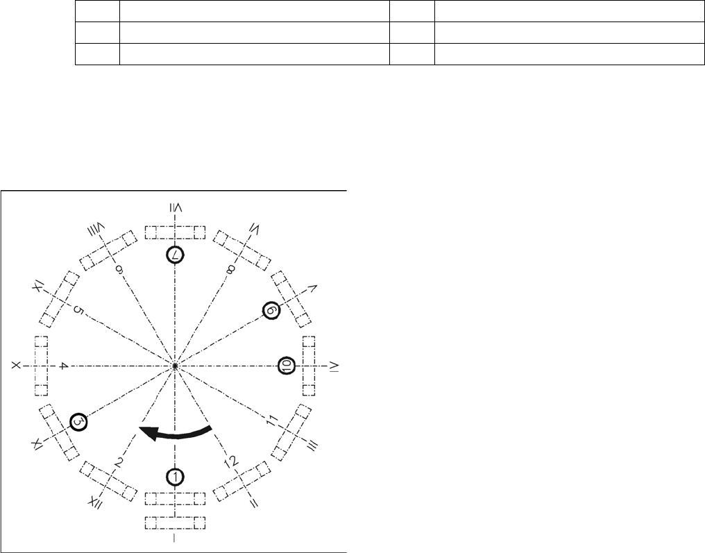
1 Vacuum generator 4 Air blast valve
2 Turning station (DP axis) 5 Silencer
3 Star with 12 sleeves (star axis) 6 Component Camera
Overview of functions for star stations 1 - 12
Star station 1: pickup, placement
Star station 2: no function
Star station 3: reject component
Star station 4-6: no function
Star station 7: optical centering of component
Star station 8: no function
Star station 9: rotate component
Star station 10: service position for sleeves and nozzles
Star station 11 and 12: no function (optional component
sensor)
I - XII: Segment numbering
3 Overview
3.4.8 SIPLACE Vision 3.4 Assemblies
Student Guide SIPLACE D-Series (FSE) 41
Star station 9:
▪ Pickup cycle
The nozzle is rotated into the "pickup" position.
▪ Placement cycle
The component is rotated into the correct placement angle with the help of the DP axis.
Between star station 11&12
▪ The "presence" and "height" of the component at the nozzle is checked by the component sensor
(optional).
3.4.8
3.4.8 SIPLACE Vision
SIPLACE Vision
For a diagram of the camera, details and technical background, refer to the chapter "Communication and
Control".
See also
16.6 SIPLACE Vision - Sensor Overview [ ➙ 279]
3.4.8.1
3.4.8.1 SIPLACE Vision - Sensor Overview
SIPLACE Vision - Sensor Overview
The digital SIPLACE Vision solution is another step towards the satisfaction of customer demands for
greater speed, flexibility and robustness.
Advantages of the digital Vision system:
▪ Robust and fast computing algorithms
▪ Flexible measurement processes
▪ Intuitive graphical user interface
▪ Geometric description of components at the machine
▪ State-of-the-art digital camera hardware
▪ Homogenous illumination of camera field of vision and components
Each C&P head has its own digital component camera.
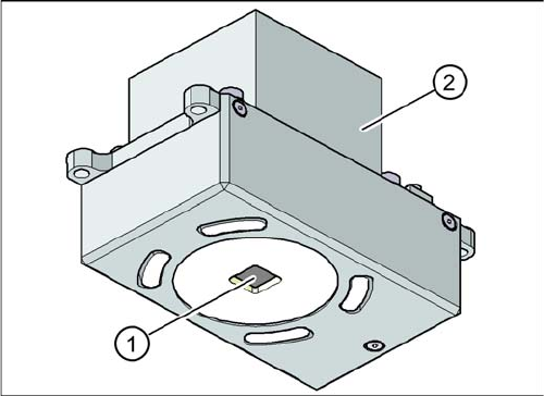
Digital PCB Camera (Type 34)
PCB camera under the gantry (X-axis)
Legend
1. PCB camera optics and illumination
2. Camera amplifier