00195440-05-SG_D-Series_FSE-EN.pdf - 第66页
4 Communication and Control 4.3 CAN Bus 4.3.6 CAN I/O Module and Interface – Differences Bet ween the Various D/Di- 66 Student Guide SIPLACE D-Series (FSE) I/O module sector 4 Overview CAN I/O module Legend DIP Switch on…
4 Communication and Control
4.3.6 CAN I/O Module and Interface – Differences Between the Various D/Di-Series Machines 4.3 CAN Bus
Student Guide SIPLACE D-Series (FSE) 65
CAN-Bus-Terminal COT (Switch settings S1 at A3-component)
*1
D1/D1i/D2/D2i: WPC and sector 1
*2
D1/D1i/D2/D2i: Sector 2
4.3.6
4.3.6 CAN I/O Module and Interface – Differences Between the Various D/Di-Series Machines
CAN I/O Module and Interface – Differences Between the Various D/Di-Series Ma-
chines
The CAN interface does not have a 4-pin DIP switch at the back, despite it being shown on the corre-
sponding circuit diagrams.
CAN I/O Module (SLIO) - SIPLACE D4/D4i
There are 2 CAN Bus I/O modules in the D4/D4i machine. Both modules are absolutely identical and are
located in sectors 2 and 4.
Function
▪ Micro controller with integrated CAN controller
▪ Data memory
▪ Program memory (flash)
▪ CAN interface with 9 pin connector and address alignment
▪ 16 digital Output 24 V with status LED
▪ 24 digital Input 24 V with status LED
▪ Download interface
▪ Power supply 24 V (for D3: 24 V and 5 V)
▪ Extension on I/O module for the CAN interface (changeover tables)
8 digital inputs can be logically linked with the help of a FPGA (freely programmable gate array). The
FPGA is used for incoming security messages.
I/O module sector 2
S
Feeder table
plate
Sector 1
*1
Feeder table
plate
Sector 2
*2
Feeder table
plate
Sector 3
Feeder table
plate
Sector 4
1ON OFFON OFF
2ON ON OFF OFF
NOTICE
Assembly
If the CAN I/O module is fitted again, take care when connecting the plugs, as the greater space
around the plugs can lead to incorrect connection. Incorrect connection will lead to permanent
CAN bus malfunctions and will prevent the machine from starting again.
4 Communication and Control
4.3 CAN Bus 4.3.6 CAN I/O Module and Interface – Differences Between the Various D/Di-
66 Student Guide SIPLACE D-Series (FSE)
I/O module sector 4
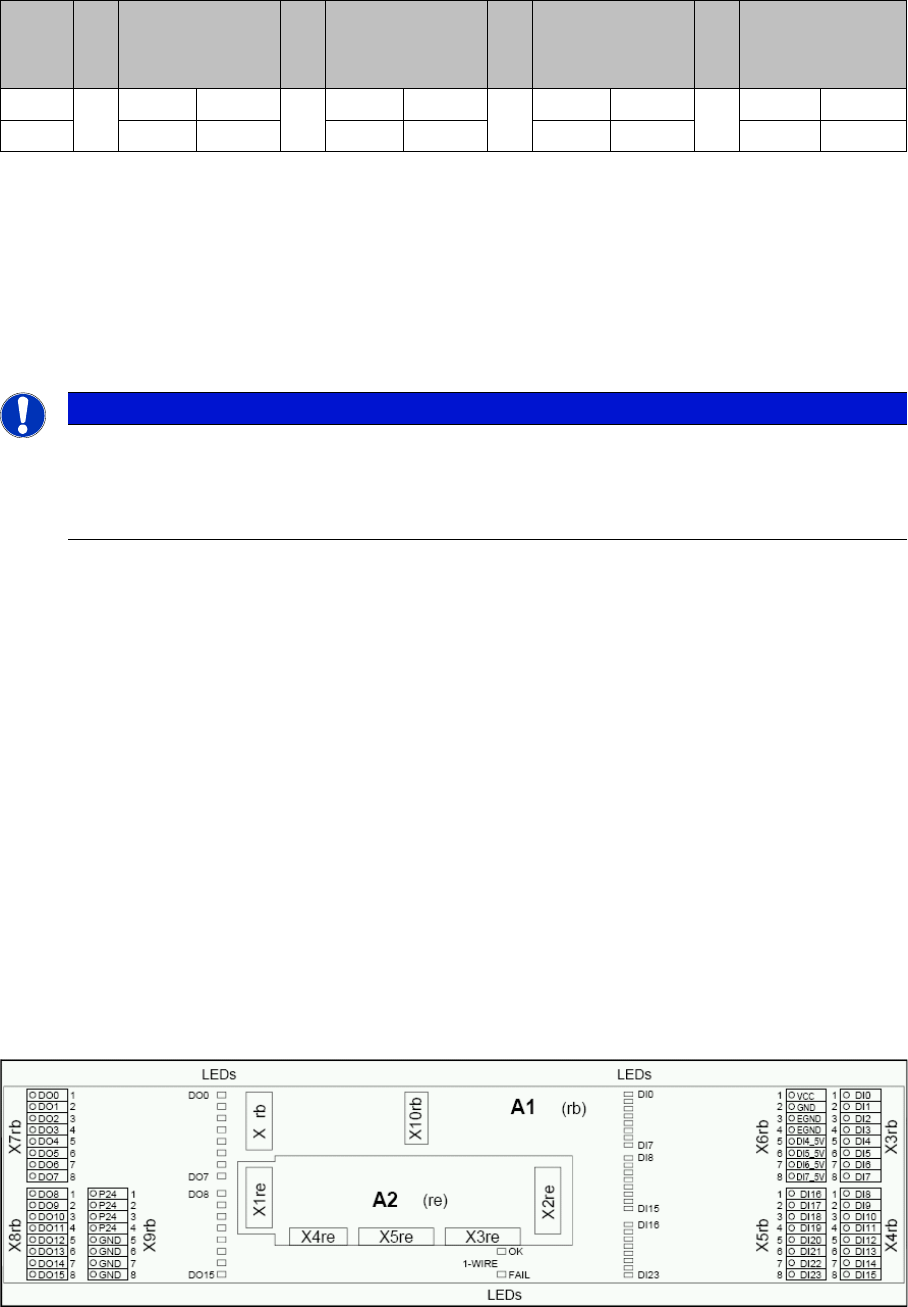
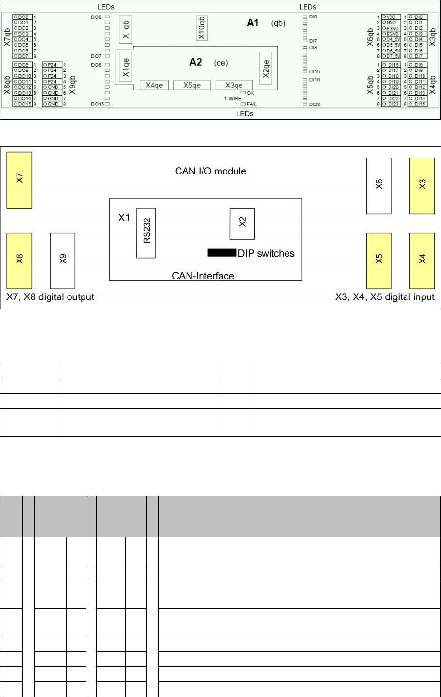
Overview CAN I/O module
Legend
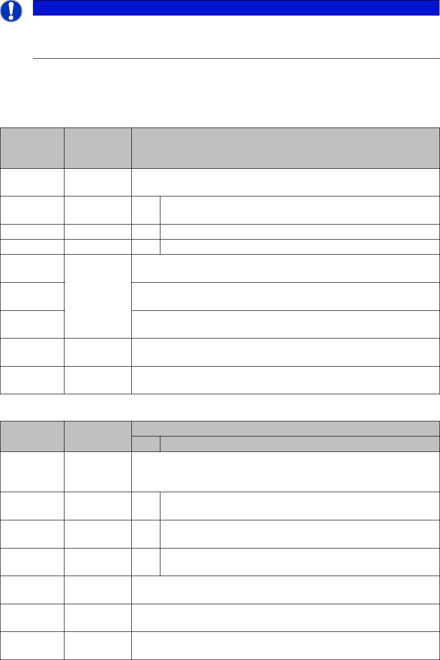
DIP Switch on the Main- and Sub Distributor
The switches on the CAN-E/A-Moduls are used to set he correct settings for the various machine types.
These setting are different from machine type to machine type
X1 CAN interface X2 Analog interface, bootstrap loader interface
X3, X4, X5 Digital inputs 24V X6 Power supply 5V
X7, X8 Digital outputs 24V X9 Power supply 24V
RS232 Analog interface, bootstrap loader
interface
S Main dis-
tributor
sector 2
Subdis-
tributor
sector 4
Comments
1O
N
ON Gateway (activate)
2OFF OFF ON: Slio emulation, OFF: CAN I/O module
3OFF OFF Transmission rate sub CAN bus for location: D1/D1i/D2/D2i: ON
(1 Mbit/s), D4/D4i: OFF (500 Kbit/s)
4O
N
OFF ON: Location sector 2, OFF: Location sector 4 (D1/D1i/D2/D2i:
OFF)
5OFF OFF Not in use
6OFF OFF ON: 1-Wire MA, OFF: 1-Wire PC
7OFF OFF Not in use
8OFF OFF Terminating resistor OFF (not used) (D1/D1i/D2/D2i: ON)
4 Communication and Control
4.3.7 File Name Codes for Downloading 4.3 CAN Bus
Student Guide SIPLACE D-Series (FSE) 67
4.3.6.1
4.3.6.1 CAN I/O Module - Inputs and Outputs
CAN I/O Module - Inputs and Outputs
4.3.7
4.3.7 File Name Codes for Downloading
File Name Codes for Downloading
The mentioned subassemblies need to be loaded with software. For details refer to SITEST.
File name codes for downloading
File name codes for downloading
NOTICE
Cause of Hazard
For the assignment of inputs and outputs on D/Di-series machines, refer to the applicable circuit
diagrams or respective texts in the SITEST I/O menu.
File name Firmware ver-
sion in SIT-
EST
Meaning of bold letters in file names
A0100208.bh
x
0.1.02.08 Machine part here 'A' general for all axis controllers
A0100208.bh
x
1 means axis controller A 362 (for S20-> HS60)
3 means axis controller A 363 (for HF series)
4 means axis controller A 364 (for D/Di and X series)
A0100208.bh
x
These "target
numbers" are
not present for
DL with SIT-
EST
0 means BIOS
A0110308.bh
x
1 means application 1
A01202DE.b
hx
2 means application 2 for VC controller of axis controller
A01202DE.b
hx
02DE means firmware version
A01202DE.b
hx
bhx is not a
ZIP file!
bhx or hex is the file name extension
File name Other descrip-
tion
HW components as letters
HW version details
B0100201.he
x
Auto down-
load if re-
quired
B means communication unit on changeover table.
B01xxxxx.he
x
SIPLACE changeover table on HM/HS/D4/D4i machine
(500Kbit/s)
B02xxxxx.he
x
SIPLACE changeover table on HF/ D1/2 / D1i/2i machine (1Mbit/
s)
B04xxxxx.he
x
X changeover table on X machine
C0100201.he
x
* C means star axis C&P 20
D03200DE.b
hx
D means D-axes C&P12/6
E0100200.bh
x
E means I/O assembly controller