00195440-05-SG_D-Series_FSE-EN.pdf - 第44页
3 Overview 3.4 Assemblies 3.4.8 SIPLACE Vision 44 Student Guide SIPLACE D-Series (FSE) Digital Component Cam era C&P12 (Type 28) Technical data Technical data for camera type 28 Component Camera C&P 12 (Optional,…
3 Overview
3.4.8 SIPLACE Vision 3.4 Assemblies
Student Guide SIPLACE D-Series (FSE) 43
Inkspot Criteria
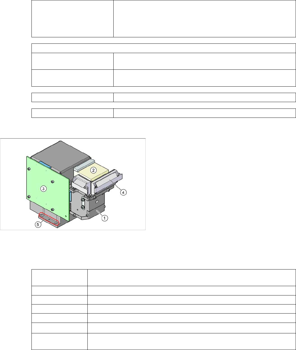
Optional Digital Component Camera C&P12 (Type 38)
Technical data
Technical data for camera type 38
Methods ▪ Synthetic fiducial detection procedures
▪ Middle gray value
▪ Histogram method
▪ Template matching
Size of fiducial shapes or structures
Synthetic Fiducials For dimensions of synthetic fiducials, see "3.4.8.1.1.2 Fiducial Criteria"
[➙42].
Other methods Min. 0,3 mm
max. 3 mm
Cover material Covers well
Recognition time Depending on method, 20 ms - 0.2 s
Component camera as option on the C&P12 head
Legend
1. Component camera optics and illumination
2. Camera amplifier
3. Illumination control
4. Flat ribbon cable holder for C&P head leads
5. Camera fixtures
2 x fixture drillings and 1 x centering drilling each on
both sides
The camera type 38 can be recognized by its type label.
Component dimen-
sions
0.2 x 0.1 mm
2
to 16 x 16 mm
2
Component range 0.2 x 0.1 mm² (01005) to PLCC36 (32R)
Min. lead pitch 0,1 mm
Min. ball pitch 0.25 mm
Min. ball diameter 0.14 mm
Field of vision
20.5 x 20.5 mm
2
Method of illumina-
tion
Front lighting (6 programmable options on 4 levels )
3 Overview
3.4 Assemblies 3.4.8 SIPLACE Vision
44 Student Guide SIPLACE D-Series (FSE)
Digital Component Camera C&P12 (Type 28)
Technical data
Technical data for camera type 28
Component Camera C&P12 (Optional, Type 29)
Technical data
Technical data for camera type 29
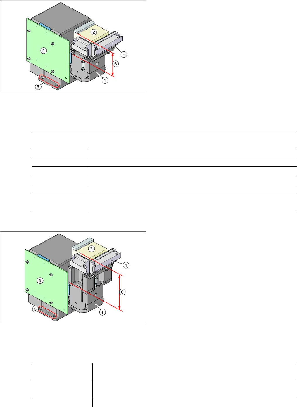
Component camera as default on the C&P12 head
Legend
1. Component camera optics and illumination
2. Camera amplifier
3. Illumination control
4. Flat ribbon cable holder for C&P head leads
5. Camera fixtures
2 x fixture drillings and 1 x centering drilling each on
both sides
6. The low construction helps you to differentiate cam-
era type 28 from camera type 29.
Component dimen-
sions
0.5 x 0.5 mm
2
to 18.7 x 18.7 mm
2
Component range 0402 to PLCC44 incl. BGA, µBGA, flip-chip, TSOP, QFP, SO to SO32, DRAM
Min. lead pitch 0.5 mm
Min. ball pitch 0.45 mm
Min. ball diameter 0.25 mm
Field of vision 24.5 x 24.5 mm2
Method of illumina-
tion
Front lighting (6 programmable options on 4 levels )
Component camera as default on the C&P12 head
Legend
1. Component camera optics and illumination
2. Camera amplifier
3. Illumination control
4. Flat ribbon cable holder for C&P head leads
5. Camera fixtures
2 x fixture drillings and 1 x centering drilling each on
both sides
6. The high construction helps you to differentiate cam-
era type 29 from camera type 28.
Component dimen-
sions
0.3 x 0.3 mm
2
to 27 x 27 mm
2
Component range
0201 to 27 x 27 mm
2
PLCC, SO, QFP, TSDP, SOT, MELF, CHIP, IC, BGA
Min. lead pitch 0.3 mm
3 Overview
3.4.8 SIPLACE Vision 3.4 Assemblies
Student Guide SIPLACE D-Series (FSE) 45
Component Camera C&P12 (Optional, Type 30)
Technical data
Technical data for camera type 30
Min. ball pitch
0.25 mm for component < 18 x 18 mm
2
0.35 mm for component ≥ 18 x 18 mm
2
Min. ball diameter
0.14 mm for component < 18 x 18 mm
2
0.2 mm for component ≥ 18 x 18 mm
2
Field of vision
31 x 31 mm
2
Method of illumination Front lighting (6 programmable options on 4 levels )
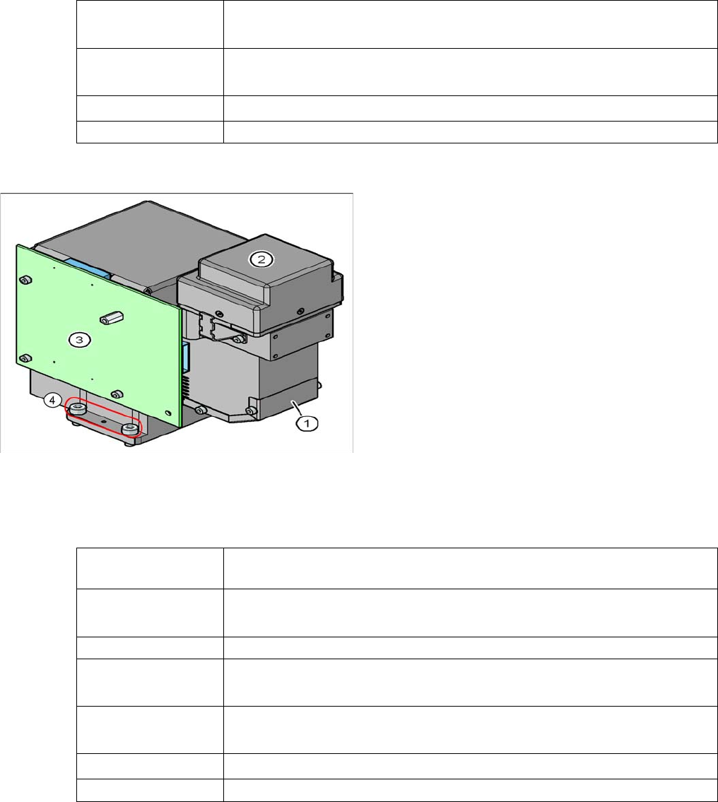
Component camera as default on the C&P12 head
Legend
1. Component camera optics and illumination
2. Camera amplifier
3. Illumination control
4. Camera fixtures
2 x fixture drillings and 1 x centering drilling each on
both sides
Component dimen-
sions
0.18 x 0.18 mm
2
to 27 x 27 mm
2
Component range
01005 to 27 x 27 mm
2
CHIP, PLCC, SO, QFP, TSDP, SOT, MELF, IC, BGA
Min. lead pitch 0.25 mm
Min. ball pitch
0.25 mm for component < 18 x 18 mm
2
0.35 mm for component ≥ 18 x 18 mm
2
Min. ball diameter
0.14 mm for component < 18 x 18 mm
2
0.2 mm for component ≥ 18 x 18 mm
2
Field of vision
32.7 x 32.7 mm
2
Method of illumination Front lighting (5 programmable options on 5 levels )