00195440-05-SG_D-Series_FSE-EN.pdf - 第18页
2 Operational Safety 2.4 Safety Equipment 2.4.1 Switches and Buttons on the Placement Machine 18 Student Guide SIPLACE D-Series (FSE) Position of switches and buttons – View of the PCB output side (D4i) Legend 1. Main sw…
2 Operational Safety
2.4.1 Switches and Buttons on the Placement Machine 2.4 Safety Equipment
Student Guide SIPLACE D-Series (FSE) 17
2.4
2.4 Safety Equipment
Safety Equipment
2.4.1
2.4.1 Switches and Buttons on the Placement Machine
Switches and Buttons on the Placement Machine
2.4.1.1
2.4.1.1 Position of Switches and Buttons on the Placement Machine
Position of Switches and Buttons on the Placement Machine
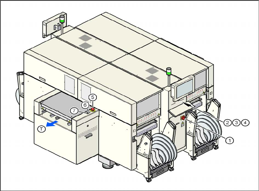
Position of switches and buttons - View of the PCB output side (D4)
2 Operational Safety
2.4 Safety Equipment 2.4.1 Switches and Buttons on the Placement Machine
18 Student Guide SIPLACE D-Series (FSE)
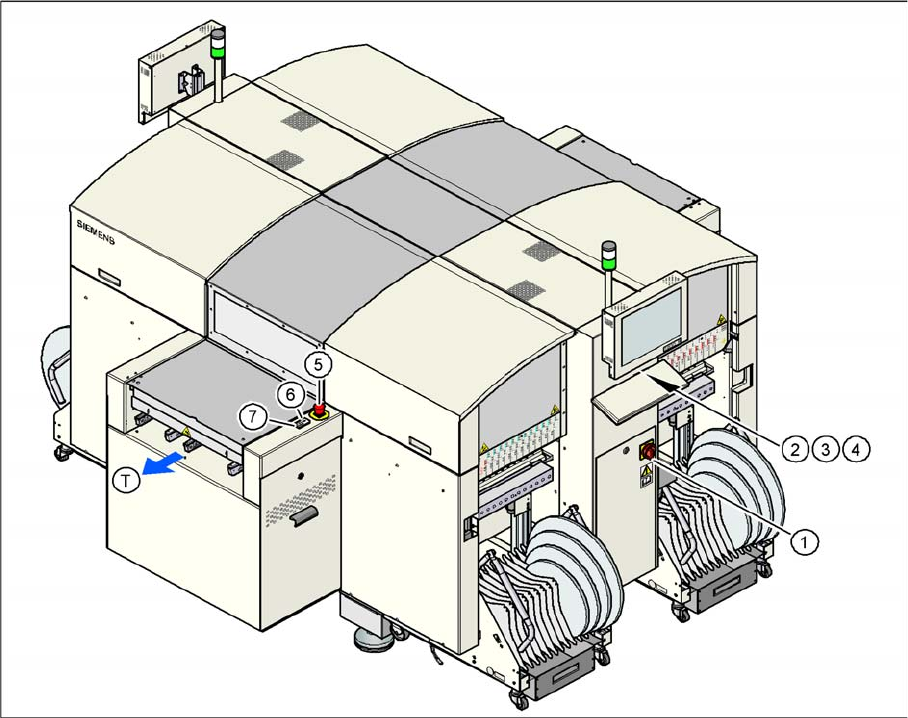
Position of switches and buttons – View of the PCB output side (D4i)
Legend
1. Main switch
2. Stop button (black) on the operator panel on the power supply side
3. Start button (white) on the operator panel on the power supply side
4. Component counter on the operator panel on the power supply side
5. Emergency stop button on the output side
6. Start button (white) on the output side
7. Stop button (white) on the output side
T = PCB direction of transport
2 Operational Safety
2.4.1 Switches and Buttons on the Placement Machine 2.4 Safety Equipment
Student Guide SIPLACE D-Series (FSE) 19
2.4.1.2
2.4.1.2 Position of Protective Switches on the Placement Machine
Position of Protective Switches on the Placement Machine
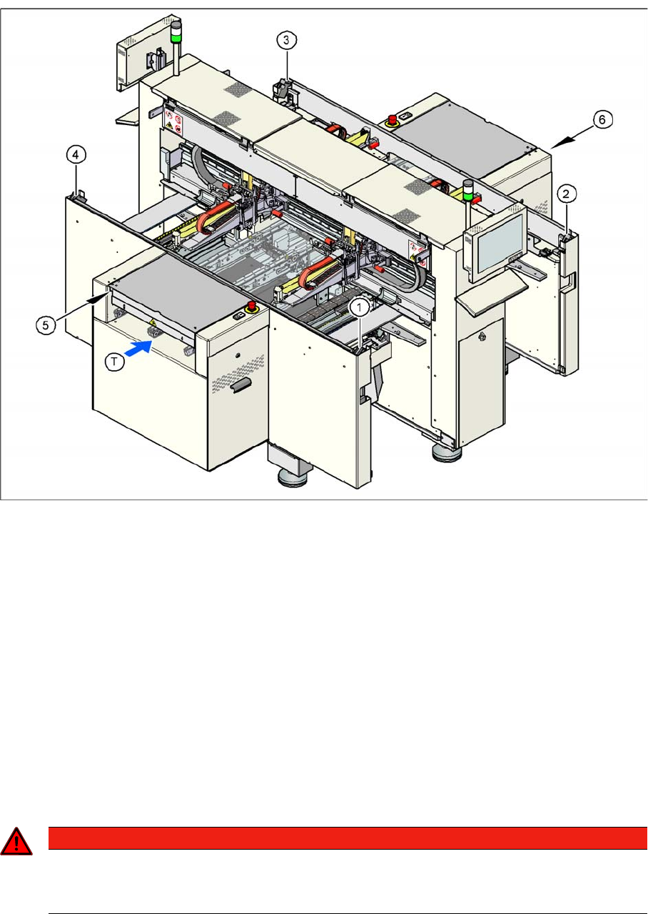
Position of protective switches on the placement machine (example of D4/D4i shown)
Legend
1. Protective cover switch, location 1
2. Protective cover switch, location 2
3. Protective cover switch, location 3
4. Protective cover switch, location 4
5. Protective switch for the cover flap on the PCB conveyor input side
6. Protective switch for the cover flap on the PCB conveyor output side
T = PCB direction of transport
2.4.1.3
2.4.1.3 Functions
Functions
Main power switch in the OFF position
The main power switch disconnects the three phases L1, L2, and L3 from the power supply.
▪ Cable connection terminals L1, L2, and L3 of the Q1 main power switch
▪ Z1 line filter
▪ Service socket BU1
DANGER
Cause of Hazard
The following components still carry potentially lethal voltages even if the main power switch is
switched off: