00195440-05-SG_D-Series_FSE-EN.pdf - 第162页
9 C&P Placement Heads 9.3 Travel Profile - Pickup 9.3.1 Z Axis Down 162 Student Guide SIPLACE D-Series (FSE) 9.3 9 . 3 T r a v e l P r o f ile - P ic k u p Travel Profile - Pickup 9.3.1 9 . 3 . 1 Z A x is D o w n Z A…

9 C&P Placement Heads
9.2.13 BE-Presence 9.2 Placement Procedure
Student Guide SIPLACE D-Series (FSE) 161
Air blast control for placing back (not rejecting) with the C&P6/12 head
▪ (4) Entry and description as in (1)
▪ (5) Entry and description as in (2)
▪ (6) Entering "151-255" means: air blast valve will be switched off at a 180° rotation of the stepping
motor.
9.2.13
9.2.13 BE-Presence
BE-Presence
Im Ablauf einer Bestücksequenz des C&P12 wird geprüft ob das Vakuumsystem in Ordnung ist bzw. es
wird geprüft ob das BE korrekt an der Pipette vorhanden ist.
9.2.13.1
9.2.13.1 Component Sensor Functional Description
Component Sensor Functional Description
The component sensor for the C&P12 head functions according to the shadow casting principle, to de-
termine the height of the component on the nozzle. This means that the nozzle shadow is compared to
the shadow caused by the nozzle with component.
Measurement is performed "on the fly", during star rotation.
Conditions for measurement:
▪ The component sensor is fitted.
▪ The component sensor is configured in SIPLACE Pro and SITEST.
▪ The nozzle is longer than 12 mm and casts a shadow in the sensor.
▪ The component on the nozzle is still within the 5mm measuring range
(nozzle length in sensor + component height < 5 mm).
▪ The component has been selected for measurement in the component sensor (in order to measure
either the component presence or component height).
Component presence check modes (SIPLACE Pro programming)
Measurement procedure:
▪ Compare the "length of empty nozzle before pickup" with the "nozzle length during reference run".
▪ Compare the component on the nozzle before placement (depends on operating mode) with the
"length of the empty nozzle before pickup".
▪ After 350 head cycles, the "nozzle length during reference run" is measured again.
NOTICE! The BE sensor C&P12-Head does not measure 0,4x0,2 mm (01005).. The empty
nozzle is scanner measured before and after placement in this way the component placement is ensured
SIPLACE Pro Station software Measurement result
Advanced BE-Sensor Anwesenheitsprüfung nur vor
dem Bestücken und nur beim C&P12
und Vakuummessung nach Abholen
> nozzle length + component height - com-
ponent height tolerance
No vacuum BE-Sensor Anwesenheitsprüfung beim
C&P12 nur vor dem Bestücken.
(Beim C&P12 ohne BE-Sensor und beim
C&P6 keinerlei BE-
Anwesenheitsprüfung.)
Component
height (com-
ponent thick-
ness)
BE-Sensor Höhenmessung bei C&P12
nur vor dem Bestücken
> nozzle length + component height - com-
ponent height tolerance
and
< nozzle length + component height + com-
ponent height tolerance
9 C&P Placement Heads
9.3 Travel Profile - Pickup 9.3.1 Z Axis Down
162 Student Guide SIPLACE D-Series (FSE)
9.3
9.3 Travel Profile - Pickup
Travel Profile - Pickup
9.3.1
9.3.1 Z Axis Down
Z Axis Down
9.3.1.1
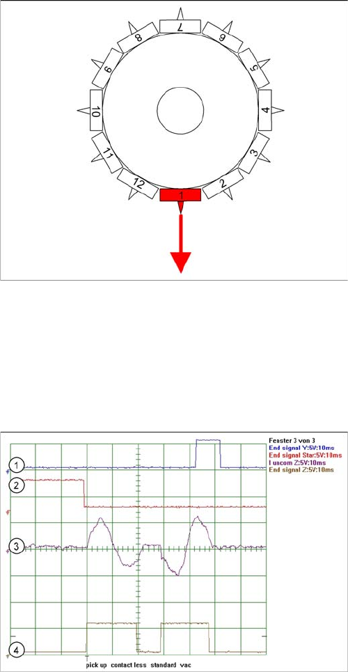
9.3.1.1 Detailed Standard Pickup Procedure: Z-Axis Down
Detailed Standard Pickup Procedure: Z-Axis Down
Star position 0°: detailed pickup procedure: Z-axis down
Start gantry axes to pickup position of next feeder and
communication with changeover table: Start signal to
gantry axes
▪ Start signal X & Y axis to next feeder/this opens the
feeder flap
End position signal for X/Y and star axes:
▪ End position signal for star axis
▪ Enables vacuum query: "segment airtight?" before
pickup
▪ X/Y end position signals available.
Z-axis starts:
▪ Z-axis starts positioning downwards
Light barrier (LB) up switches:
▪ Release signal for function LB down, (after a waiting
period of approx. 3.6 ms, depending on the DIP
switch, special function, currently not active as a de-
fault)
LB down switches:
▪ End position signal for positioning Z-axis down
▪ and valve positioning drive ON for vacuum.
Legend
1. End position signal for Y-axis (position to feeder pick-
up position)
2. End position signal for star axis
3. Uncommutated motor current for Z-axis
4. End position signal for Z-axis
Section 1: move down
Section 2: move up
8 ms after the end position signal for the Z-axis, the
system switches over to vacuum and the Z-axis is re-
started and moved upwards.
9 C&P Placement Heads
9.3.1 Z Axis Down 9.3 Travel Profile - Pickup
Student Guide SIPLACE D-Series (FSE) 163
9.3.1.2
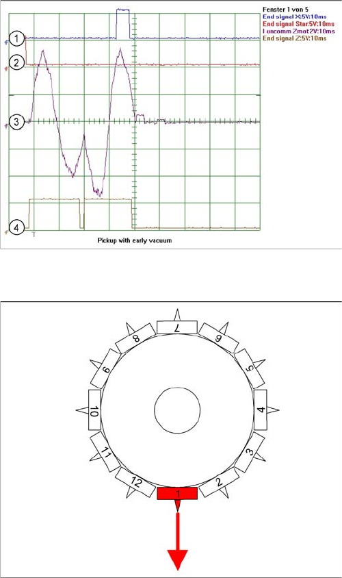
9.3.1.2 Special Mode "Contactless Pickup" Z-Axis Down
Special Mode "Contactless Pickup" Z-Axis Down
Pickup procedure for "contactless pickup":
▪ Start gantry axes to pickup position of feeder and communication with changeover table:
– Start signal to gantry axes
– Signal for next feeder / this opens the feeder flap
▪ End position signal for X/Y and star axes:
– End position signal for star axis
– Enables vacuum query: "segment airtight?" before pickup
– X/Y end position signals available.
▪ Z-axis starts with operating mode "positioning type - absolute" to saved nominal height:
– Positioning of Z-axis down
▪ Light barrier (LB) up switches:
– Release for function LB down (although not needed))
▪ Axis controller switches:
– When the taught pickup height is reached, end position signal for Z-axis positioning is issued.
▪ The machine controller switches:
– Valve positioning drive for switching over to vacuum ON.
Legend
1. End position signal for X-axis (position to feeder pick-
up position)
2. End position signal for star axis
3. Uncommutated motor current for Z-axis
4. End position signal for Z-axis
Section 1: move down
Section 2: move up
In contrast to the previous diagram, a delay of typical-
ly 2 ms occurs for early vacuum.
Special mode Z-axis down with "early vacuum ON in top
position"
In the case of LRU/LRL 503 and SIPLACE Pro, contact-
less pickup can only be programmed in the CS for SR/
MC 503 stations and higher.
When the component track, for which contactless pickup
has been programmed, is accessed for the first time, the
following is performed:
▪ The Z-axis is taught the pickup height with increased
force. The Z-axis moves until it mechanically stops.
▪ This pickup height is then reduced by 1.13 mm (602)
to give the nominal height (path of segment deceler-
ation and ...) and is saved. The component used for
the teaching procedure is rejected.