00195440-05-SG_D-Series_FSE-EN.pdf - 第246页
14 SITEST 14.2 Calibration 14.2.3 C&P Head 246 Student Guide SIPLACE D-Series (FSE) ▪ Each mag azine must at least h av e a nozzle presen t and configur ed (1) in ga rage 1 . 14.2.3 1 4 . 2 . 3 C & P H e a d C&am…
14 SITEST
14.2.1 Calibration - General Sequence 14.2 Calibration
Student Guide SIPLACE D-Series (FSE) 245
14.2.1
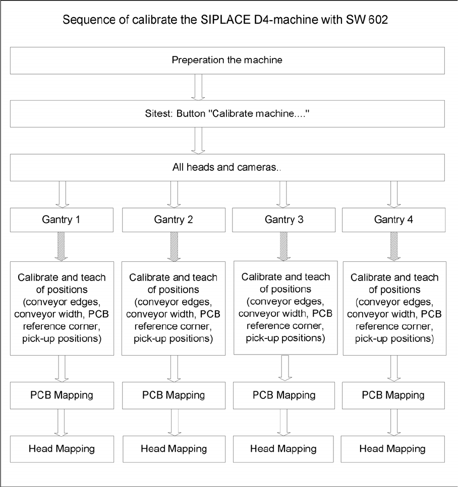
14.2.1 Calibration - General Sequence
Calibration - General Sequence
General sequence to calibrate the machine
14.2.2
14.2.2 Requirements for Calibration of Nozzle Changers in the SIPLACE D/Di Machines
Requirements for Calibration of Nozzle Changers in the SIPLACE D/Di Machines
► Start SITEST.
► by selecting the menu items MAIN VIEW, Overall reference run, to start the reference run for all gan-
tries and heads.
► Configure the nozzle changer and check the component levels.
Precondition for calibrating the nozzle changer
▪ Each magazine in the NC must be configured with a nozzle type.
▪ There should be no nozzle at segment 1 .
14 SITEST
14.2 Calibration 14.2.3 C&P Head
246 Student Guide SIPLACE D-Series (FSE)
▪ Each magazine must at least have a nozzle present and configured (1) in garage 1 .
14.2.3
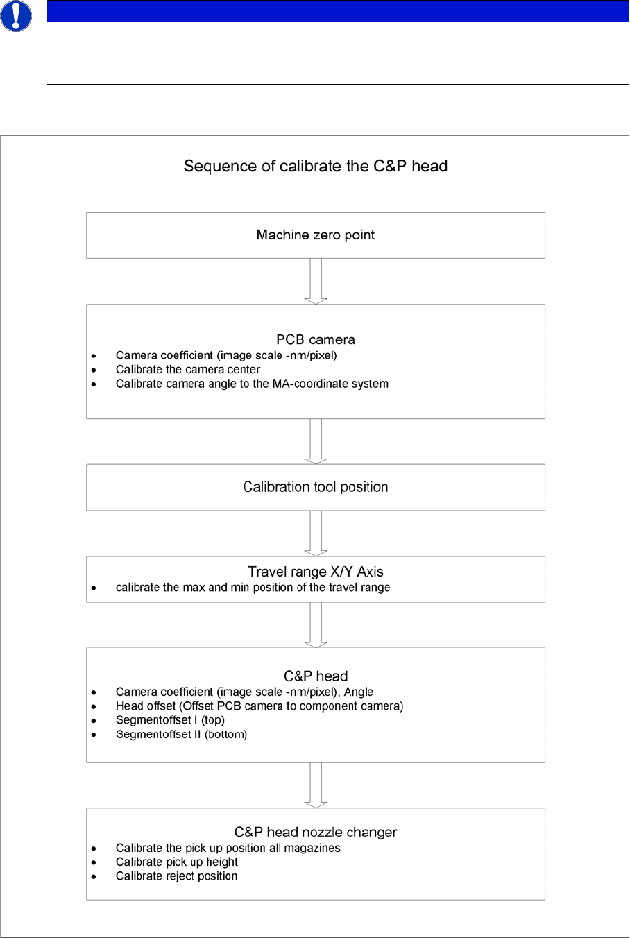
14.2.3 C&P Head
C&P Head
Sequence of C&P head calibration
NOTICE
Cause of Hazard
When configuring the C&P12 (only), you can also set all magazines to "empty" and the head to
"full".
14 SITEST
14.3.1 Travel Range 14.3 Calibration Basics
Student Guide SIPLACE D-Series (FSE) 247
14.3
14.3 Calibration Basics
Calibration Basics
14.3.1
14.3.1 Travel Range
Travel Range
14.3.1.1
14.3.1.1 Position of Calibration Tool
Position of Calibration Tool
▪ Calibrate the X and Y pick up position of the calibration tool.
14.3.2
14.3.2 Component Camera
Component Camera
▪ The Pixel size of the CCD sensors of the camera is determined in µm. Measured and calculated with
Ax/Bx/Cx/Ay/ByCy calibration values. Saved in camera.xml as: XU_Pixel / YU_Pixel in nm
▪ The pixel size is:
approx. 49700 nm for component camera SST 28 (for 12-segment head)
approx. 26760 nm for component camera SST 29 (for 6-segment head/12-segment head option)
approx. 17220 nm for component camera SST 23 (for 20-segment head)
▪ The camera center is determined.
▪ The Mounting angle of the CCD-chip in the camera to the turning level of the placement star is meas-
ured. The value is saved as Kamera_winkel (camera_angle) in the data block of the component cam-
era, in the camera.xml .
X gantry axis:
▪ The X gantry axis moves to the zero pulse, to cali-
brate the travel range and then moves on to the HW
end stoppers (limit switch). The respective gantry
axis position is recorded there.
▪ The maximum hardware travel range is set 1.5 mm
before the bumper. The software travel range value is
0.5 mm before that.
Y gantry axis:
▪ The Y gantry axis moves to the zero pulse, to cali-
brate the travel range and then moves on to the outer
HW end stoppers on the left or right (limit switch). The
respective gantry axis position is recorded there.
▪ The maximum hardware travel range is set 1.5 mm
before this position. The software travel range value
is 1.5 mm before that.
▪ In the case of the Y axes, only the outer HW end stop-
pers are approached in each case. The other end po-
sition of the travel path is calculated. This gives a
travel range distance to the other gantry of about 35
mm.
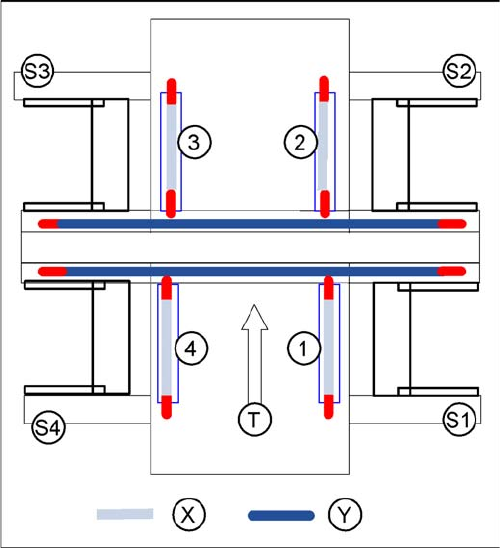
Legend
▪ 1-4:Gantry 1-4
▪ S1 - S4:Sector 1-4
▪ X:Travel range X
▪ Y:Travel range Y
▪ T:Transport direction