SIPLACE CA4 V2规格说明书.pdf - 第11页
11 Placement heads SIPLACE MultiStar (CPP M) SIPLACE MultiStar (CPP M) With compo nent camera type 45 Component range a a) Please note that the placeable component range is also affected by the pad geometry, the customer…
10
Placement heads
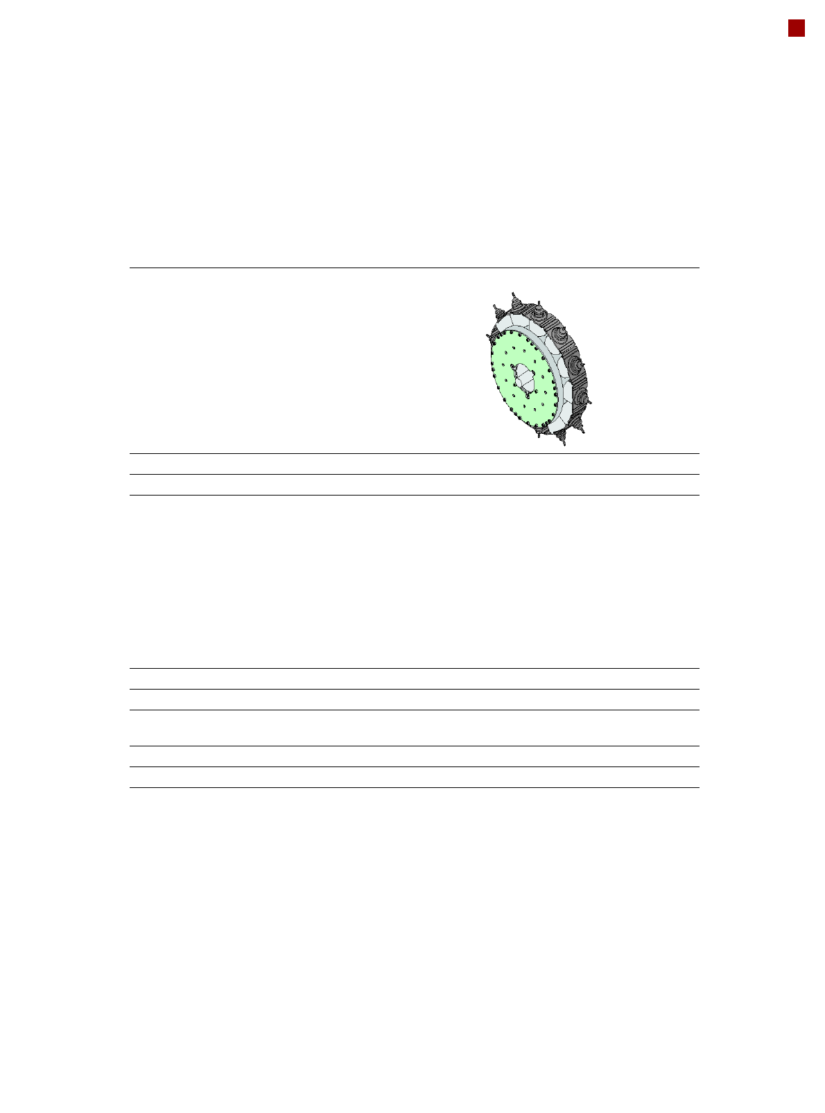
SIPLACE SpeedStar (C&P20 M2)
SIPLACE SpeedStar (C&P20 M2)
With component camera
type 48
With component camera
type 49
Component range
a
a) Please note that the placeable component range is also affected by the pad geometry, the customer-specific stan-
dards, the component packaging tolerances and the component tolerances.
0.12 mm x 0.12 (0201 metric)
to 2220, Melf, SOT, SOD,
Bare-Die, Flip-Chip
0.12 mm x 0.12 (0201 metric)
to 2220, Melf, SOT, SOD,
Bare-Die, Flip-Chip
Component spec.
Max. height
Min. lead pitch
Min. lead width
Min. ball pitch
Min. ball diameter
Min. dimensions
Max. dimensions
Max. weight
4 mm
70 µm
30 µm
100 µm
50 µm
120 µm x 120 µm
6 mm x 6 mm
1 g
4 mm
b
50 µm
25 µm
50 µm
25 µm
80 µm x 80 µm
6 mm x 6 mm
1 g
b) Component camera, type 49 requires the correct nozzle length according to component thickness due to focus range
±0.3 mm.
Set-down force 1,3 N ± 0,5N (standard value)
0,5 N- 4,5 N
Touchless Placement
Nozzle types 40xx 40xx
X/Y accuracy See section Placement performance and accuracy on page 8
Angular accuracy ± 0.2°at 3σ ± 0.2°at 3σ
Illumination levels 5 5
11
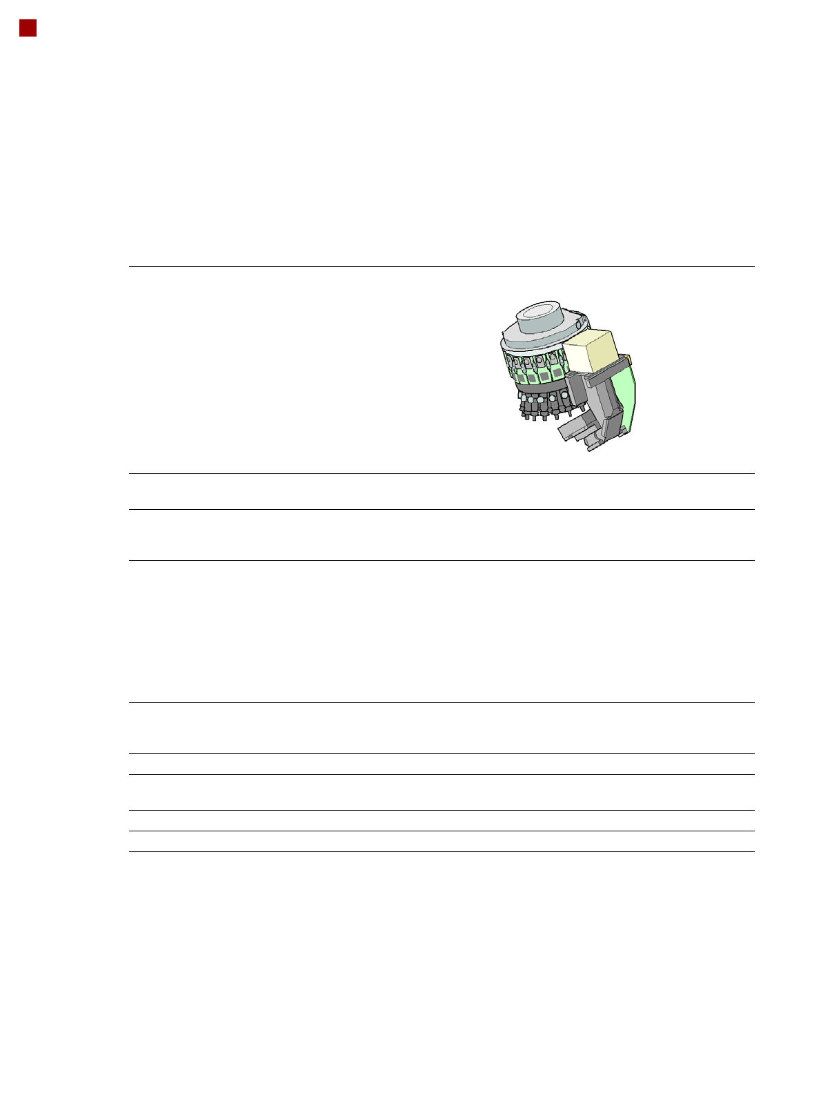
Placement heads
SIPLACE MultiStar (CPP M)
SIPLACE MultiStar (CPP M)
With component camera type 45
Component range
a
a) Please note that the placeable component range is also affected by the pad geometry, the customer-
specific standards, the component packaging tolerances and the component tolerances.
01005 to 15 mm x 15 mm
b
b) Larger components up to 27 mm x 27 mm available on request
Component spec.
Max. height
c
Min. lead pitch
Min. lead width
Min. ball pitch
Min. ball diameter
Min. dimensions
Max. dimensions
Max. weight
c) CPP M head: in low installation position.
6,0 mm
250 µm / 120 µm
d
50 µm
140 µm
70 µm
110 µm x 110 µm
15 mm x 15 mm
4 g
d) Only available for components which are within the camera range of focus: ± 1.3 mm.
Set-down force 1.0 - 10 N
Nozzle types 20xx, 28xx
X/Y accuracy See section Placement performance and accura-
cy on page 8
Angular accuracy ± 0.1°at 3σ
Illumination levels 5
12
Placement heads
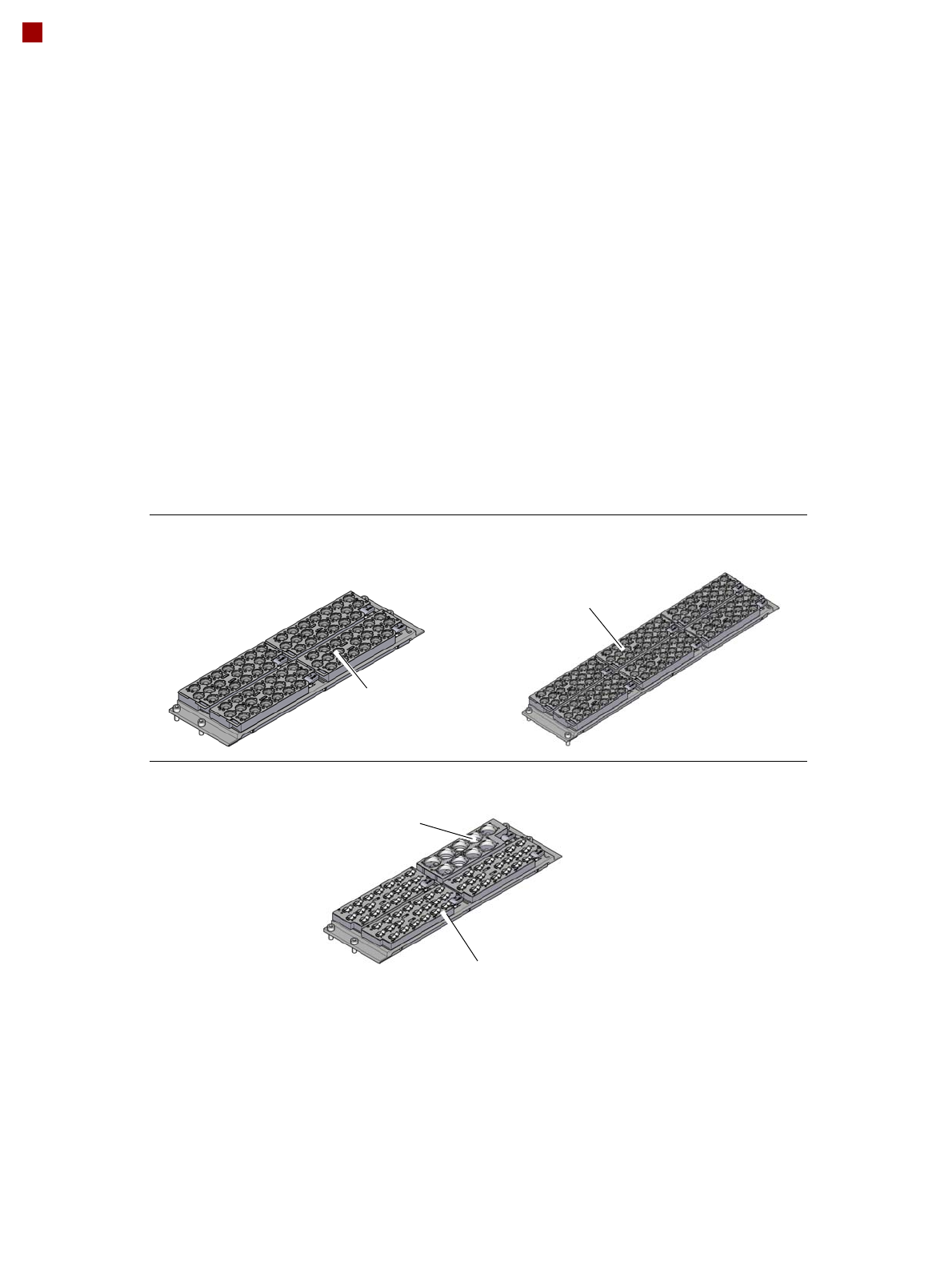
Nozzle changer
Nozzle changer for the SIPLACE SpeedStar
Nozzle changer for the SIPLACE MultiStar
4 magazines for 20 nozzles of
type 40xx
6 magazines for 20 nozzles of
type 40xx
Magazine for 9 nozzles of
type 28xx
Magazine for 20 nozzles of type 20xx
Description
Nozzle changers increase the flexibility of the placement heads when it comes to processing
different components. The nozzle configuration can be rapidly adjusted to changing place-
ment jobs. Precisely defined positions and perfect nozzle seat in the garage ensure minimum
radial eccentricity on the placement head.
The nozzle changers feature a monitoring circuit. This checks whether the nozzle magazines
are seated correctly on the mount. In addition, the nozzle changer recognizes whether the
magazines are for 40xx, 20xx or 28xx nozzles by the code.