SIPLACE CA4 V2规格说明书.pdf - 第40页
40 SIPLACE Vision Barcode types Technical data 1D barcode s QR codes Code typ es Code 39 Code 93 Code 128 EAN-8 (AddOn 2, AddOn 5), E AN-13 (AddOn 2, AddOn 5) Interleaved 2 of 5 Minimum width of bar 5 pixels If the quali…

39
SIPLACE Vision
Barcode types
Technical data
The PCB camera can read a
Data matrix code, a 1D bar-
code or a QR code. The
data can be used for trace-
ability purposes.
The barcode can be on the
board itself or on a compo-
nent. In addition, it is also
possible to attach a barcode
label to a board or a compo-
nent and to then read this
barcode label with the PCB
camera, directly after place-
ment. The focal height must
be taken into account during
reading, if there is a barcode
or barcode label on the top of
a component.
General information for all barcode types
Data matrix codes
Ambiguity No read errors are issued if multiple valid barcode symbols are found in a
particular region of interest (ROI). In this case, there is no clear rule, defin-
ing which of these valid barcode symbols would be read.
Ambiguity can be avoided by:
• Using a suitable ROI size
ASCII null characters Barcode information should not contain any ASCII null characters (ASCII
NULL), as the 0 byte in the software is interpreted as an final (end) char-
acter.
Code type Only data matrix ECC 200 is supported.
No. rows/columns All combinations of rows/columns as defined in the standard will be
accepted, including rectangular symbols and large symbols with multiple
data areas.
Minimum dot size 5 pixels
Symbol angle All symbol angles will be accepted.
Inverse symbols Inverse symbols (light modules on a dark background) will be accepted.
Mirrored symbols Mirrored symbols will be accepted.
Ratio of column width to row
height
1/2
≤ (column width) / (row height) ≤ 2
Region of Interest (ROI) The area in which the barcode is searched for (ROI) should not exceed the
following values:
Width of ROI
≤ 6 * width of barcode symbol
Height of ROI ≤ 6 * Height of barcode symbol

40
SIPLACE Vision
Barcode types
Technical data
1D barcodes
QR codes
Code types Code 39
Code 93
Code 128
EAN-8 (AddOn 2, AddOn 5), EAN-13 (AddOn 2, AddOn 5)
Interleaved 2 of 5
Minimum width of bar 5 pixels
If the quality of the mark is sufficient, the width can be reduced down to 3
pixels.
Minimum height of symbol 5% of length of whole symbol.
Symbol angle All symbol angles will be accepted.
Inverse symbols Light bars on a dark background will be accepted.
(Station software version 708.0 or higher required)
Mirrored symbols Mirrored symbols will be accepted.
(this corresponds to a rotation of 180 degrees for 1D codes)
Region of Interest (ROI) The area on the board, in which the barcode is searched for (ROI), should
not exceed the following values:
ROI (direction of reading)
≤ 3 * symbol width
ROI (vertical to direction of reading) ≤ 10 * symbol width
Code type QR code in accordance with ISO/IEC 18004 model 2.
Station software version 711.0 or higher required
No. rows/columns All versions still defined in the standard (i.e. number of rows/columns) are
accepted.
Minimum dot size 5 pixels
Symbol angle All symbol angles will be accepted.
Inverse symbols Inverse symbols (light modules on a dark background) will be accepted.
Mirrored symbols Mirrored symbols will be accepted.
Ratio of column width to row
height
1/2
≤ (column width) / (row height) ≤ 2
Region of Interest (ROI) The area in which the barcode is searched for (ROI) should not exceed the
following values:
Width of ROI ≤ 6 * width of barcode symbol
Height of ROI ≤ 6 * Height of barcode symbol
41
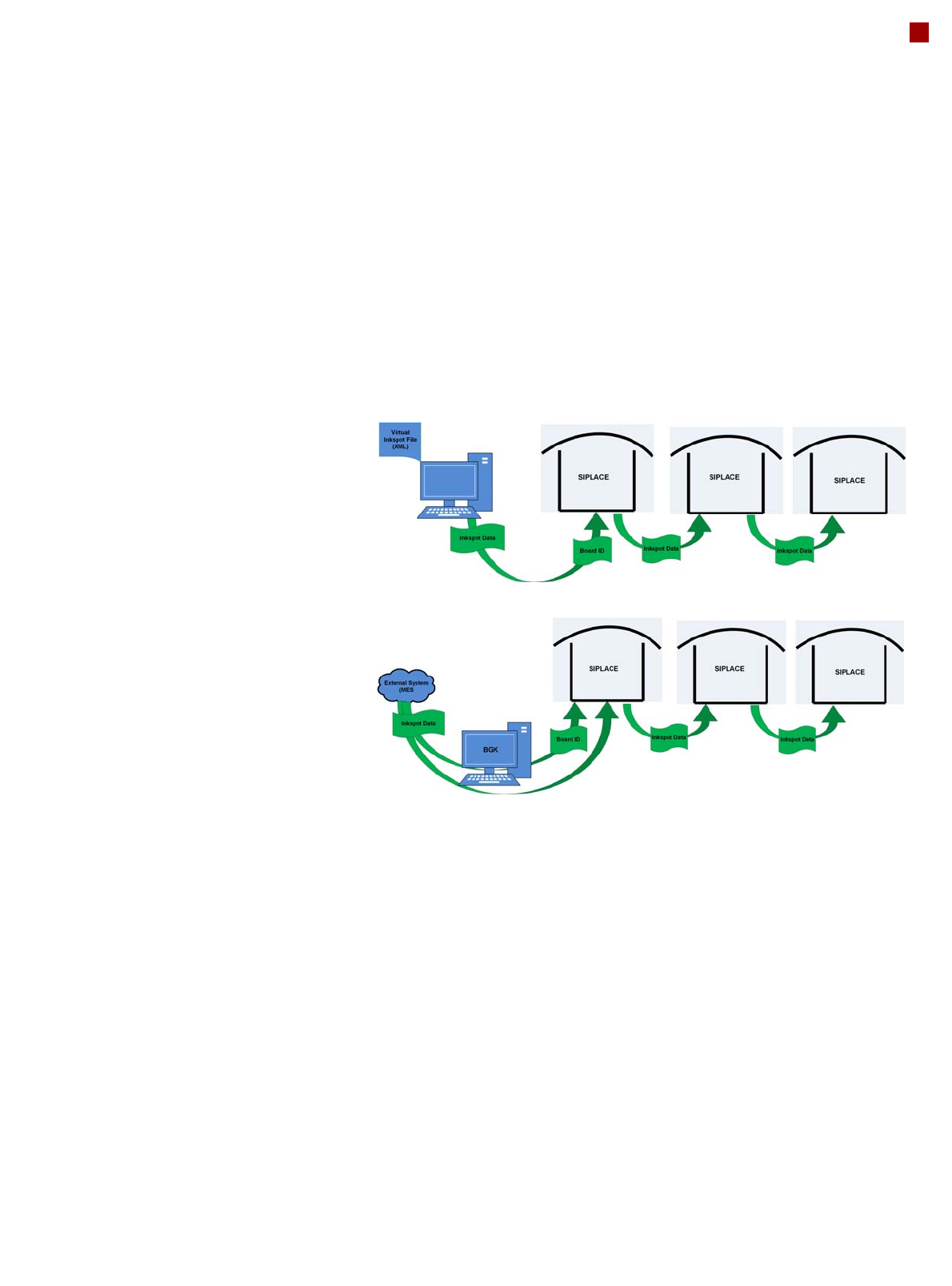
Virtual Inkspot Handler (VIH)
The virtual inkspot handler
(VIH) allows you to scan in
inkspots from an external
system.
This option can be used for
external systems to define
which panels are to be
produced and which to be
omitted. A panel is a specific
part of a printed circuit
board. This concept is much
more flexible than the
physical inkspot concept.
It can be integrated into the
ongoing production process,
if external systems
individually decide whether
each panel it is in a good or
bad state and whether
additional processing steps
are to be omitted or not.
The boards are typically
measured by the external
system and the information
about which panels are good
or bad is then available.
The use of this information
via VIH offers the benefit that
no physical inkspots need to
be read by the PCB camera.
This improves performance,
particularly for boards with a
large number of panels.
This option can also be used
if the panels do not have
room for a physical inkspot.
Workflow VIH with XML file
Workflow VIH with MES and BoardGateKeeper (BGK)
Process Data Interfaces (PDI)
The process data interface (PDI), which can be addressed via
the OIB interface, enables you to access not only the trace-
ability data of the components placed but also various process
parameters for the component placement. The PDI makes
over 40 process attributes per placement position available,
such as:
• Pickup (actual pick position, pickup location ID)
• Dipping (result, timestamp)
• Vision measuring (result plus camera ID)
• Placement (actual place position, ref. desig., vacuum val-
ues)
The data packages contain the data for each board and stop-
per position.
Each individual data package contains a maximum of 200
placement positions.