SIPLACE CA4 V2规格说明书.pdf - 第19页
19 Single lane and dual lane conveyor PCB warpage PCB warpage during placement To avoid impairing the placement quality and speed, we recommend using a PCB support e.g. Smart Pin Support so that the PCB warpag e downward…
18
Single lane and dual lane conveyor
PCB warpage
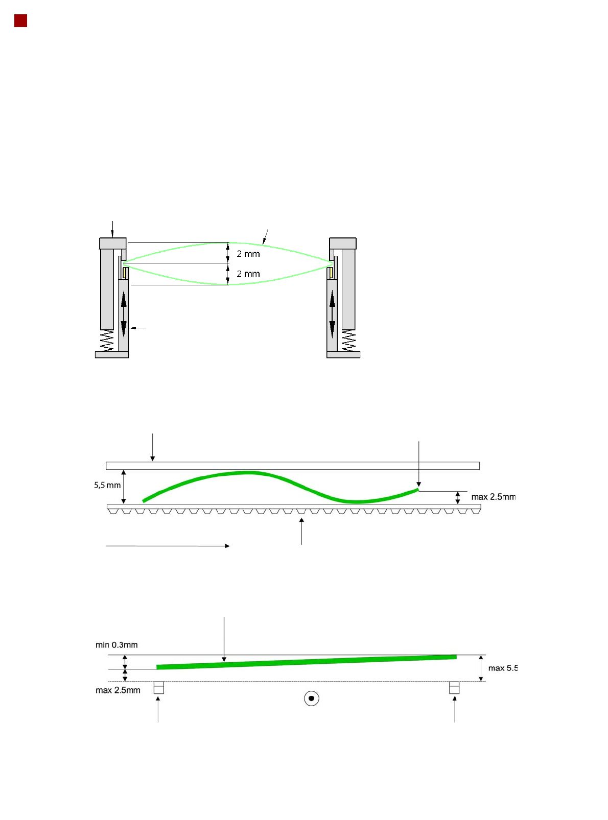
PCB warpage across the direction of travel
max. 1 % of the PCB diagonal, but not
exceeding 2 mm
PCB warpage on the conveyor
Fixed clamped edge
Movable clamping device
PCB
Fixed clamped edge
Conveyor belt
PCB transport direction
Front board edge
Front board edge
PCB warpage in direction of travel + PCB thickness < 5.5
mm
Bending up of front board edge max. 2.5 mm
Left conveyor belt
Right conveyor belt
PCB transport direction
19
Single lane and dual lane conveyor
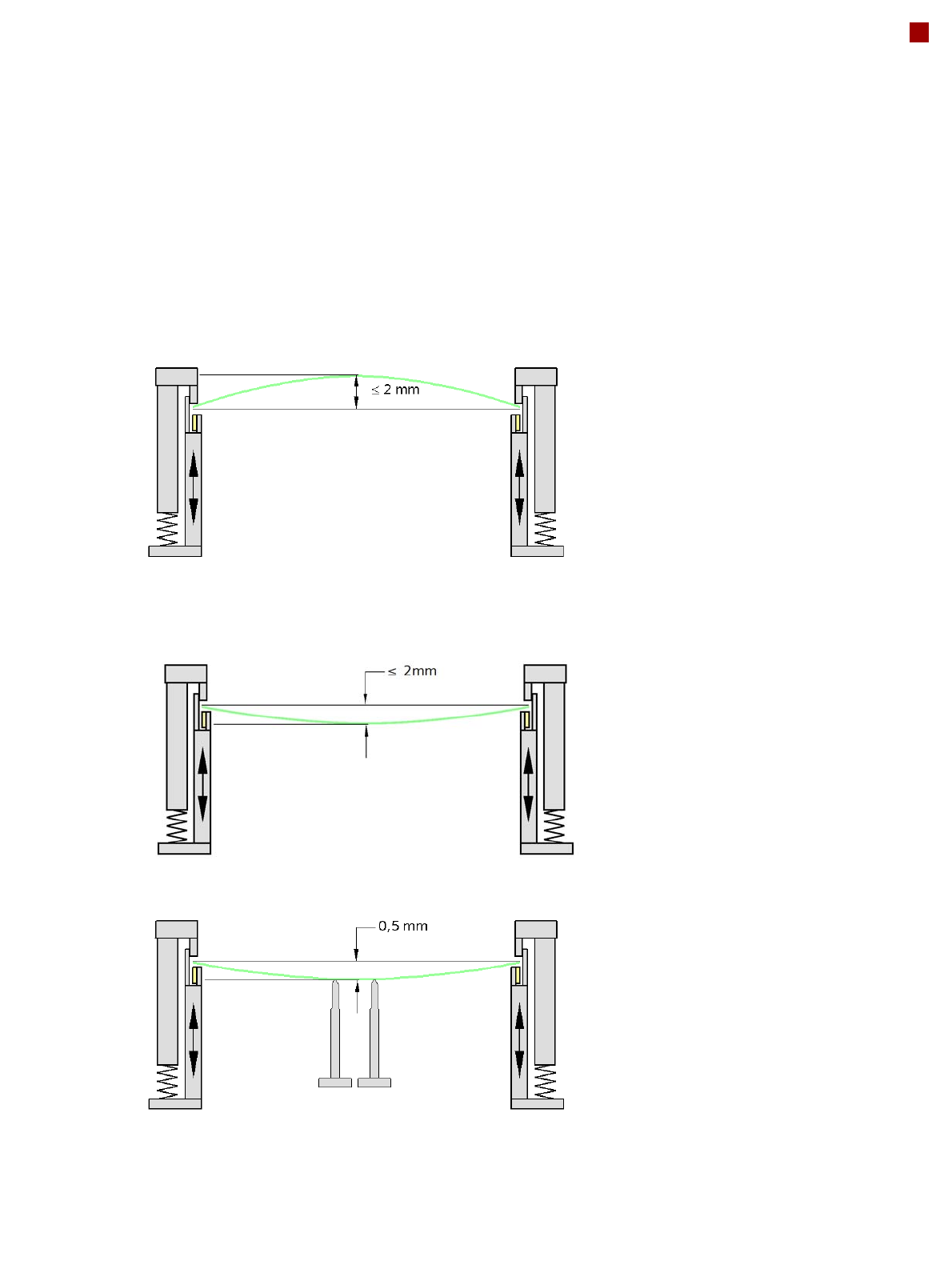
PCB warpage
PCB warpage during placement
To avoid impairing the placement quality and
speed, we recommend using a PCB support e.g.
Smart Pin Support so that the PCB warpage
downwards does not exceed 0.5 mm.
PCB warpage up, max. 2 mm
PCB support
PCB warpage down, max. 2 mm
Changes in the surface position are automatically applied by the functions for learning the height.
20
Panel lane and wafer lane conveyor
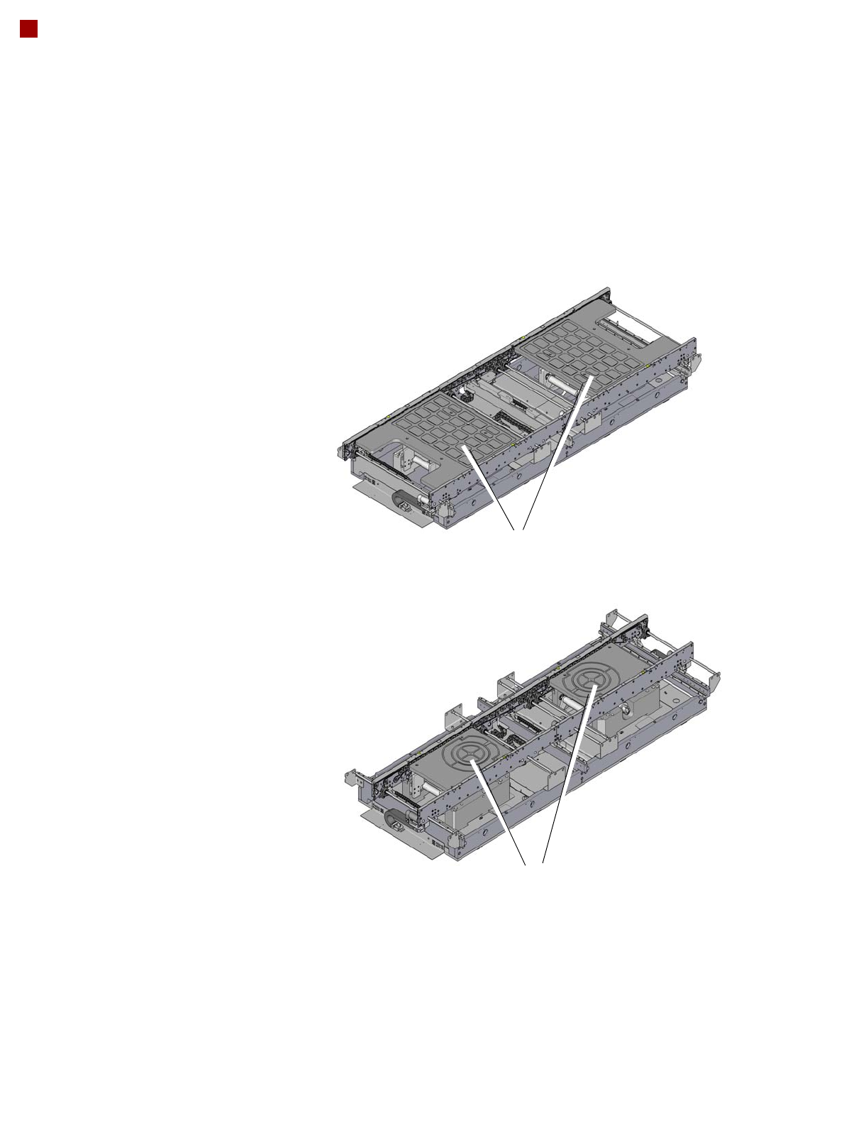
Panel lane conveyor
There are two different vac-
uum tooling options available
for the panel lane conveyor:
• Vacuum tooling
L625 x W615 for wide
workpiece carriers
• Vacuum tooling
L330 x W315 for narrow
workpiece carriers
Panel lane conveyor with vacuum tooling L625 x W615
Panel lane conveyor with vacuum tooling L330 x W315