SIPLACE CA4 V2规格说明书.pdf - 第22页
22 Panel lane and wafer lane conveyor Technical data Panel lane conveyor Wafer lane con- veyor Vacuum tooling L330 x W315 Vacuum tooling L625 x W615 Vacuum tooling DM 300 Wor kpiece carri er dimen sions Width x length to…
21
Panel lane and wafer lane conveyor
Wafer lane conveyor
There are two different vac-
uum tooling options for the
different workpiece carrier
thicknesses available for the
wafer lane conveyor:
• DM 300 ST 0.55 for thin
workpiece carriers
• DM 300 ST 1.2 for thick
workpiece carriers
The vacuum tooling DM 300
can be temperature-con-
trolled. The corners feature
glass fiducials to compen-
sate the precise position of
the vacuum tooling in the
machine and the deformation
of the machine.
A temperature regulating
system to keep the set pro-
cess temperature constant is
available for the tempera-
ture-controlled vacuum tool-
ing.
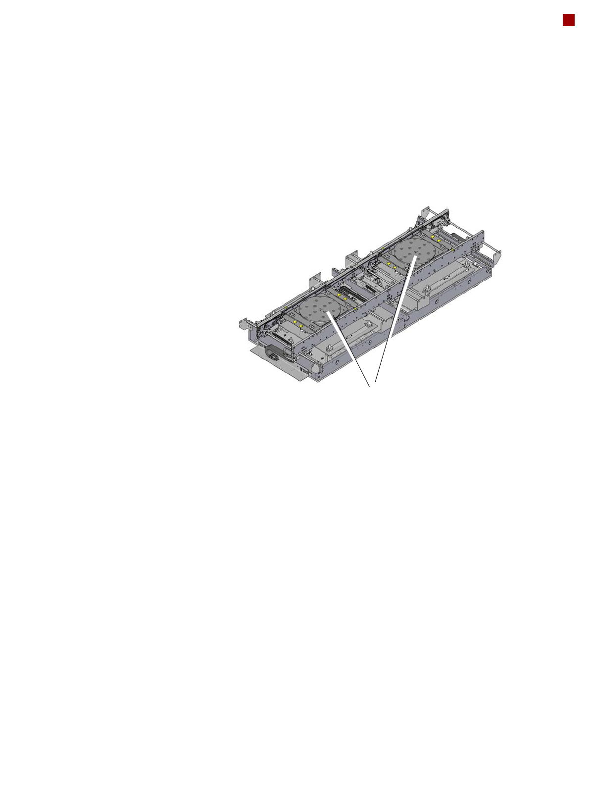
Wafer lane conveyor with vacuum tooling DM 300

22
Panel lane and wafer lane conveyor
Technical data
Panel lane conveyor Wafer lane con-
veyor
Vacuum tooling
L330 x W315
Vacuum tooling
L625 x W615
Vacuum tooling
DM 300
Workpiece carrier dimensions
Width x length to
330 mm x
330 mm
to
650 mm x 685
mm
a
a) With long board option (LBO)
--
Diameter -- -- to 300 mm
b
b) In the case of rectangular workpiece carriers, 330 mm x 330 mm is possible
Automatic electrical width adjustment? Standard
Workpiece thickness
Vacuum tooling L330 x W315
Vacuum tooling L625 x W615
Vacuum tooling DM 300 ST 0.55
Vacuum tooling DM 300 ST 1,25
0.3 mm to 4.5 mm
0.3 mm to 4.5 mm
--
--
--
--
0.55 mm
1.25 mm
Workpiece carrier warpage See page 24
Workpiece carrier weight
c
Cycle time 60 min / 3 years service life
Cycle time 10 min / 3 years service life
Cycle time 0,25 min / 3 years service life
c) The workpiece weight value refers to the weight of the workpiece plus the weight of the components.
Max. 10.0 kg
Max. 6.0 kg
d
Max. 3.0 kg
d
d) Shorter cycle times could lead to reduced service life or an increased need for spare parts.
Max. 10.0 kg
Max. 6.0 kg
d
Max. 3.0 kg
d
--
--
Max. 3.0 kg
d
Space on the workpiece carrier underside 0.0 mm
Workpiece carrier transportation height
Option
Standard
Option SMEMA
900 mm
930 mm
950 mm
Type of interface SMEMA or IPC-HERMES-9852
Component-free PCB handling edge 3 mm
Workpiece carrier changeover time < 1.5 seconds
23
Panel lane and wafer lane conveyor
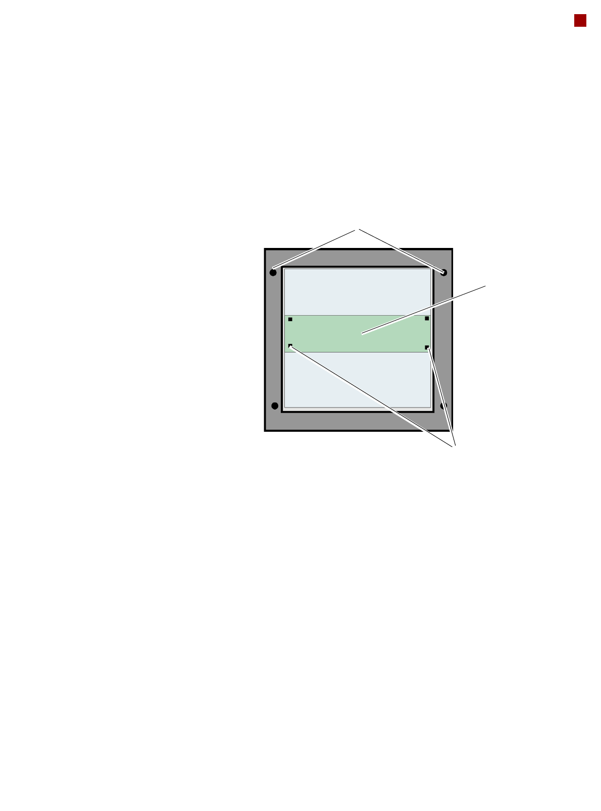
Wafer and panel level fan out process
Panel level fan out is used
for large workpiece carriers.
A double-sided thermal
release foil is attached to a
workpiece carrier (e.g. made
of steel or glass) and place-
ment is performed on this.
The panel level fan out
mode means that part of the
workpiece carrier is placed in
the first placement area and
the remaining part in the sec-
ond placement area. To
achieve the required accu-
racy, the fiducials on the
workpiece carrier are only
used for rough position rec-
ognition. These fiducials for
rough position searching
must be within an overlap-
ping area. Two fiducials are
enough. Four components
with fiducial structures are
then placed in this overlap-
ping area and measured for
fine position recognition pur-
poses. Other possible or
required fiducials are then
placed as references, in
addition to the fiducials
already placed. In the sec-
ond placement area, the four
fiducials already placed are
measured first, before pro-
ceeding as in the first place-
ment area.
Wafer level fan out is used
for smaller workpiece carri-
ers with different thick-
nesses.
The vacuum tooling used
can be temperature-con-
trolled.
The Wafer level fan out pro-
cess is available with Gas
station mode.
Wafer level fan out with
gas station mode
In Gas station mode, two
workpiece carriers moved
into the machine at the same
time. The first workpiece car-
rier is conveyed into the sec-
ond placement area, the
following workpiece carrier to
the first placement area.
These two workpiece carri-
ers are then clamped into
place at the same time.
This prevents the clamping
procedure from affecting the
accuracy of the other work-
piece carrier.
The two workpiece carriers
are placed parallel to one
another. One prerequisite for
Gas station mode, is that
the setup in the first and sec-
ond placement area is the
same.
Fiducials for rough position recognition on the workpiece carrier (rough position)
Overlapping area
Components placed for measuring the fine
position.