SIPLACE CA4 V2规格说明书.pdf - 第44页
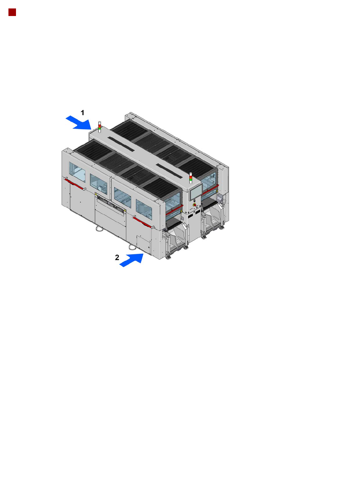
44 Technical data Electrical connection and compressed air supply 1 = Electrical connection 2 = Compressed a ir connection The connections are run into the machine from below and then co nnected to the power supply or pn…
43
Technical data
Electrical Ratings and Compressed Air Supply
SIPLACE CA4 V2
Electrical ratings
Supply voltage Fuse
Main power supply 3 x 380 V~ to 3 x 415 V~ ± 10 %; 50/60 Hz
3 x 200 V~ to 3 x 220 V~ ± 10 %; 50/60 Hz
a
a) With options package
3 x 16A characteristic C
3 x 15A characteristic C
b
b) e.g. Siemens circuit breakers in accordance with IEC and UL 489 (order no.: 5SJ4 316-7HG42)
or
EATON Industries circuit breaker FAZ-C16/3-NA 16A 3p (UL 489, CSA C22.2 no. 5, IEC 60947-2)
Mains power con-
nection
Without cable
Cable 5 x 4 mm² WITH CEE plug, red 16 A (in accordance with IEC 60309)
(3 x 380 V~ to 3 x 415 V~)
Cable 5 x 4 mm² WITHOUT plug (3 x 200 V~ to 3 x 220 V) or (3 x 380 V~ to 3 x 415 V~)
Short circuit rating (SCCR)
c
c) With the original mains connection cable. The marked short circuit rating (SCCR) relates to the beginning of the original mains
cable. In the case of customer modifications, the factory-set length of the mains cable to the placement machine may not be
shortened nor the factory-set conductor cross-section increased, as this would have a negative impact on the short circuit rating
(SCCR).
10 kA
Energy consumption
With a vacuum pump
d
d) Vacuum pump for C&P20 M2 head only.
With two vacuum pumps *
b
Without vacuum pumps
e
e) Standard
Average apparent
power
2.5 kVA 3.85 kVA 1.3 kVA
Average effective
power
1.7 kW 2.45 kW 1.0 kW
Compressed air supply
Compressed air pressure
values
p
min
p
max
0.5 MPa = 5.0 bar
1.0 MPa = 10 bar
Operating pressure 0.48 MPa ± 0.025 MPa (4.8 bar ± 0.25 bar)
Compressed air connec-
tion
R 3/4" inner thread (pipe thread) with 1/2" hose connection
Compressed air consumption
a
a) Average consumption values.
Placement head configuration Compressed air
consumption
b
With vacuum pump
b) Under normal atmospheric conditions at 20°C and 1013 hPa.
Compressed air con-
sumption
Without vacuum pump
c
c) Optional
SIPLACE CA4 V2
C&P20 M2/&P20 M2/&P20 M2/&P20 M2
C&P20 M2/C&P20 M2/CPP M/CPP M
CPP M/CPP M/CPP M/CPP M
260 Nl/min
370 Nl/min
480 Nl/min
990 Nl/min
720 Nl/min
480 Nl/min
Compressed air specification according to ISO 8573
Particle size 0.1 µm
Particle density 0.1 mg/m³
Maximum oil content (class 1) Particle density 0.01 mg/m³
Pressure dewpoint (class 4) Dewpoint + 3°
44
Technical data
Electrical connection and compressed air supply
1 = Electrical connection
2 = Compressed air connection
The connections are run into the machine from below and then connected to the power supply
or pneumatic unit.
PLEASE NOTE:
Also observe the document "Network and compressed air configuration for SMD systems" (German+English,
item no. 00197548-xx), which is supplied with your SIPLACE machine.
45
Technical data
Dimensions and setup conditions
Length
a
With handles for side sliding doors
a) Measured at the outer contour of the machine protection.
1950 mm
2100 mm
Width
Outer contour of machine protection
With 2x SWS outermost
With 2x SWS innermost
On the component trolley and table position "outermost" (handle folded in)
On the component trolley and table position "outermost" (handle folded
out)
2740 mm
4087 mm
3778 mm
2890 mm
3640 mm
Height of machine (for PCB conveyor height 930 mm)
Up to upper edge of monitor
With 2-color indicator lamp
With 3-color indicator lamp
Without indicator lamp (height of packaging)
With opened protective cover
With opened side sliding doors
1572 mm
1794 mm
1835 mm
1600 mm
2095 mm
2105 mm
Machine ground clearance
(for PCB conveyor height 900 mm)
(for PCB conveyor height 930 mm)
(for PCB conveyor height 950 mm)
195 mm ± 15 mm
225 mm ± 15 mm
245 mm ± 15 mm
Weight
SIPLACE CA4 V2 (machine without component trolley)
SIPLACE CA4 V2 (machine with 2x SWS)
SIPLACE CA4 V2 (machine with 4x SWS)
Changeover table (X)
Changeover table (X), fully configured with feeder modules
3674 kg
4374 kg
5074 kg
95 kg
190 kg
Location
b
b) Measured at the outer contour of the machine protection and at the keyboard.
5.73 m²
Load per unit area
c
With 4 component trolley X
With 4 SWS
c) The load per unit area calculation included an additional working space of 0.5 m on each side of the machine.
6.1 kN/m²
6.88 kN/m²
Number of machine feet 6
Max. noise emissions 75 dB (A)
Room temperature Between 15°C and 35°C
Atmospheric humidity 30% to 75 % (no higher than 45% on
average to prevent any possibility of con-
densation on the machine)