SIPLACE CA4 V2规格说明书.pdf - 第9页
9 Placement performance and accuracy Pick up from the SIPLACE Wafer System Placement head types: SIPLACE S peedSt ar (C&P20 M2) SIPLACE MultiS tar (CPP M) Placement perfor mance: The placement per formance is aff ect…

8
Placement performance and accuracy
Pick up from the changeover table (SMT)
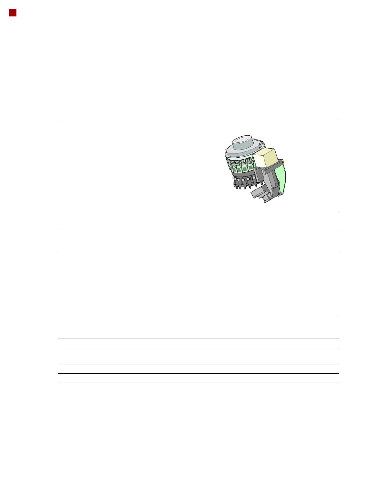
Placement head types:
SIPLACE SpeedStar (C&P20 M2)
SIPLACE MultiStar (CPP M)
Placement performance:
The placement performance is affected by the different head combinations and positions, plus the
conveyor configuration. Individual options and customized applications also influence the placement
performance. On request, SIPLACE can calculate the actual performance of your product with your
machine configuration.
Placement accuracy: SIPLACE benchmark value [components/h]
The values are measured during the machine acceptance tests and correspond to the conditions set
out in the SIPLACE scope of service and supply.
The relevant placement accuracy is only guaranteed if the room temperature is between 18°C and
28°C, does not vary by more than ± 1°C and was stable at least 48h before the placement process.
Single lane and dual lane conveyor with pickup from changeover table (SMT)
Process 4 gantries are evaluated statistically together.
The CMK value is included IN the calculation.
PA 1 PA2 Accuracy Placement
performance
2 x C&P20 M2 2 x C&P20 M2 25 µm/3σ 126,500
2 x C&P20 M2 2 x CPP M_L 25 µm/3σ 105,500
2 x CPP M_L 2 x CPP M_L 25 µm/3σ 85,500
Process: 4 gantries are evaluated statistically together.
The CMK value is included IN the calculation.
PA 1 PA2 Accuracy Placement
performance
2 x C&P20 M2 2 x C&P20 M2 20 µm/3σ 126,000
2 x C&P20 M2 2 x CPP M_L 20 µm/3σ 105,500
2 x CPP M_L 2 x CPP M_L 20 µm/3σ 85,000
Panel lane conveyor with pickup from changeover table (SMT)
Process 2 gantries work in one placement area and are evaluated independently from
one another for statistical purposes.
The CMK value is included IN the calculation.
PA 1 PA2 Accuracy Placement
performance
2 x C&P20 M2 2 x C&P20 M2 15 µm/3σ 83,000
2 x C&P20 M2 2 x CPP M_L 15 µm/3σ 73,000
2 x CPP M_L 2 x CPP M_L 15 µm/3σ 63,000

9
Placement performance and accuracy
Pick up from the SIPLACE Wafer System
Placement head types:
SIPLACE SpeedStar (C&P20 M2)
SIPLACE MultiStar (CPP M)
Placement performance:
The placement performance is affected by the different head combinations and positions, plus the
conveyor configuration. Individual options and customized applications also influence the placement
performance. On request, SIPLACE can calculate the actual performance of your product with your
machine configuration.
Placement accuracy: SIPLACE benchmark value [components/h]
The values are measured during the machine acceptance tests and correspond to the conditions set
out in the SIPLACE scope of service and supply.
The relevant placement accuracy is only guaranteed if the room temperature is between 18°C and
28°C, does not vary by more than ± 1°C and was stable at least 48h before the placement process.
Panel lane conveyor with pickup from SIPLACE Wafer System
Process
4 gantries are evaluated statistically together.
The CMK value is NOT included in the calculation.
PA 1 PA2 Accuracy Flip chip process Die attach process
2 x C&P20 M2 2 x C&P20 M2 20 µm/3σ 46,000 30,000
2 x C&P20 M2 2 x CPP M_L 20 µm/3σ 43,500 29,500
2 x CPP M_L 2 x CPP M_L 20 µm/3σ 41,000 29,000
Process 2 gantries work in one placement area and are evaluated independently from one
another for statistical purposes.
The CMK value is NOT included in the calculation.
PA 1 PA2 Accuracy Flip chip process Die attach process
2 x C&P20 M2 2 x C&P20 M2 12 µm/3σ 46,000 30,000
2 x C&P20 M2 2 x CPP M_L 12 µm/3σ 43,500 29,500
2 x CPP M_L 2 x CPP M_L 12 µm/3σ 41,000 29,000
Wafer lane conveyor with pickup from the SIPLACE Wafer System
Process 2 gantries work in one placement area and are evaluated together for statistical
purposes.
The CMK value is included IN the calculation.
PA 1 PA2 Accuracy Flip chip process Die attach process
2 x C&P20 M2 2 x C&P20 M2 10 µm/3σ 46,000 30,000
2 x C&P20 M2 2 x CPP M_L 10 µm/3σ
a
a) The accuracy of 10 µm/3σ (the CMK value IS included in the calculation) only applies to the C&P20 M2.
43,500 29,500
Process 2 gantries work in one placement area and are evaluated together for statistical
purposes.
The CMK value is NOT included in the calculation.
PA 1 PA2 Accuracy Flip chip process Die attach process
2 x CPP M_L 2 x CPP M_L 10 µm/3σ 41,000 29,000
2 x C&P20 M2 2 x CPP M_L 10 µm/3σ
b
b) The accuracy of 10 µm/3σ (the CMK value is NOT included in the calculation) only applies to the C&P20 M2.
43,500 29,500
10
Placement heads
SIPLACE SpeedStar (C&P20 M2)
SIPLACE SpeedStar (C&P20 M2)
With component camera
type 48
With component camera
type 49
Component range
a
a) Please note that the placeable component range is also affected by the pad geometry, the customer-specific stan-
dards, the component packaging tolerances and the component tolerances.
0.12 mm x 0.12 (0201 metric)
to 2220, Melf, SOT, SOD,
Bare-Die, Flip-Chip
0.12 mm x 0.12 (0201 metric)
to 2220, Melf, SOT, SOD,
Bare-Die, Flip-Chip
Component spec.
Max. height
Min. lead pitch
Min. lead width
Min. ball pitch
Min. ball diameter
Min. dimensions
Max. dimensions
Max. weight
4 mm
70 µm
30 µm
100 µm
50 µm
120 µm x 120 µm
6 mm x 6 mm
1 g
4 mm
b
50 µm
25 µm
50 µm
25 µm
80 µm x 80 µm
6 mm x 6 mm
1 g
b) Component camera, type 49 requires the correct nozzle length according to component thickness due to focus range
±0.3 mm.
Set-down force 1,3 N ± 0,5N (standard value)
0,5 N- 4,5 N
Touchless Placement
Nozzle types 40xx 40xx
X/Y accuracy See section Placement performance and accuracy on page 8
Angular accuracy ± 0.2°at 3σ ± 0.2°at 3σ
Illumination levels 5 5