00196609-0102_ AI_Optional_Stopper_SX1_2_DE+EN.pdf - 第38页
2 Assembly Instructions for Optional Stopper SIPLACE SX1/SX2 Optional stopper Edition 09/2009 38 Dual conveyor: 2 X Push the sensor rail of f the guidance bolt s. X Loosen and remove the guid ance bolt from the output si…
Optional stopper 2 Assembly Instructions for Optional Stopper SIPLACE SX1/SX2
Edition 09/2009
37
2.5 Assembly
X Undock the component trolley to give yourself good access to the working area.
X Switch the placement machine off at the main switch.
X Open the protective covers.
2
X Loosen the clamp fixtures, as the conveyor trolley needs to be accessible from the outer side
during assembly work.
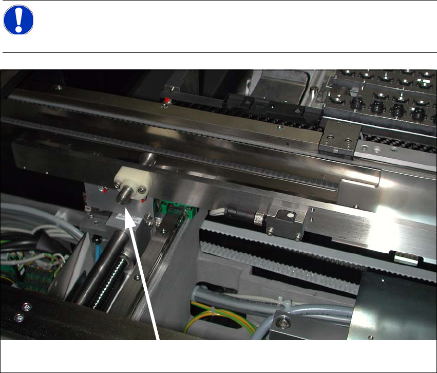
When using a single conveyor, the conveyor side can be fixed on the side of the guidance
block.
Single conveyor
2
2
2
2 Assembly Instructions for Optional Stopper SIPLACE SX1/SX2 Optional stopper
Edition 09/2009
38
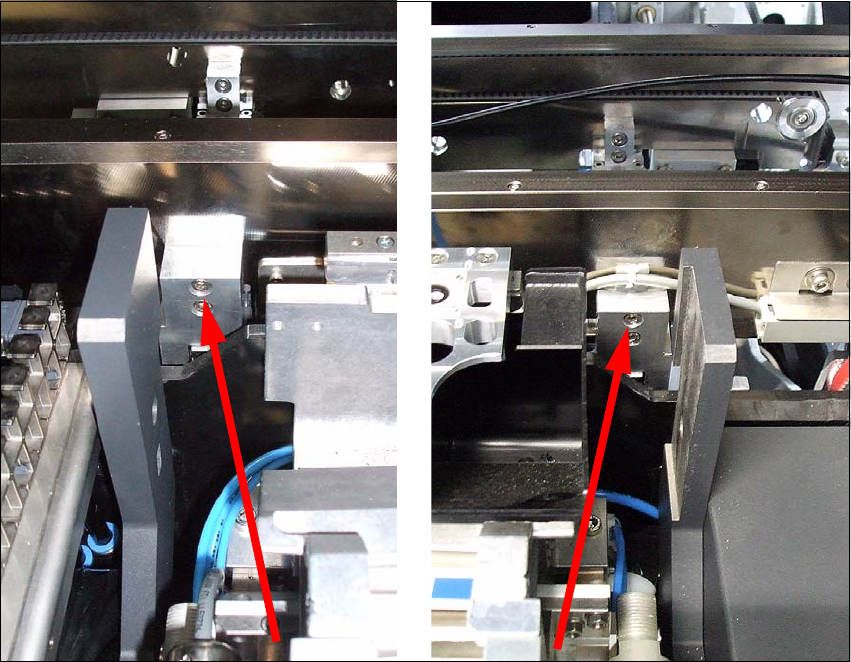
Dual conveyor: 2
X Push the sensor rail off the guidance bolts.
X Loosen and remove the guidance bolt from the output side. The screw is located on the outside
of the conveyor side.
2
2
2
NOTE:
After completing work with the software, the fixed conveyor side can be returned to its
original position. 2
Bolts 2
Optional stopper 2 Assembly Instructions for Optional Stopper SIPLACE SX1/SX2
Edition 09/2009
39
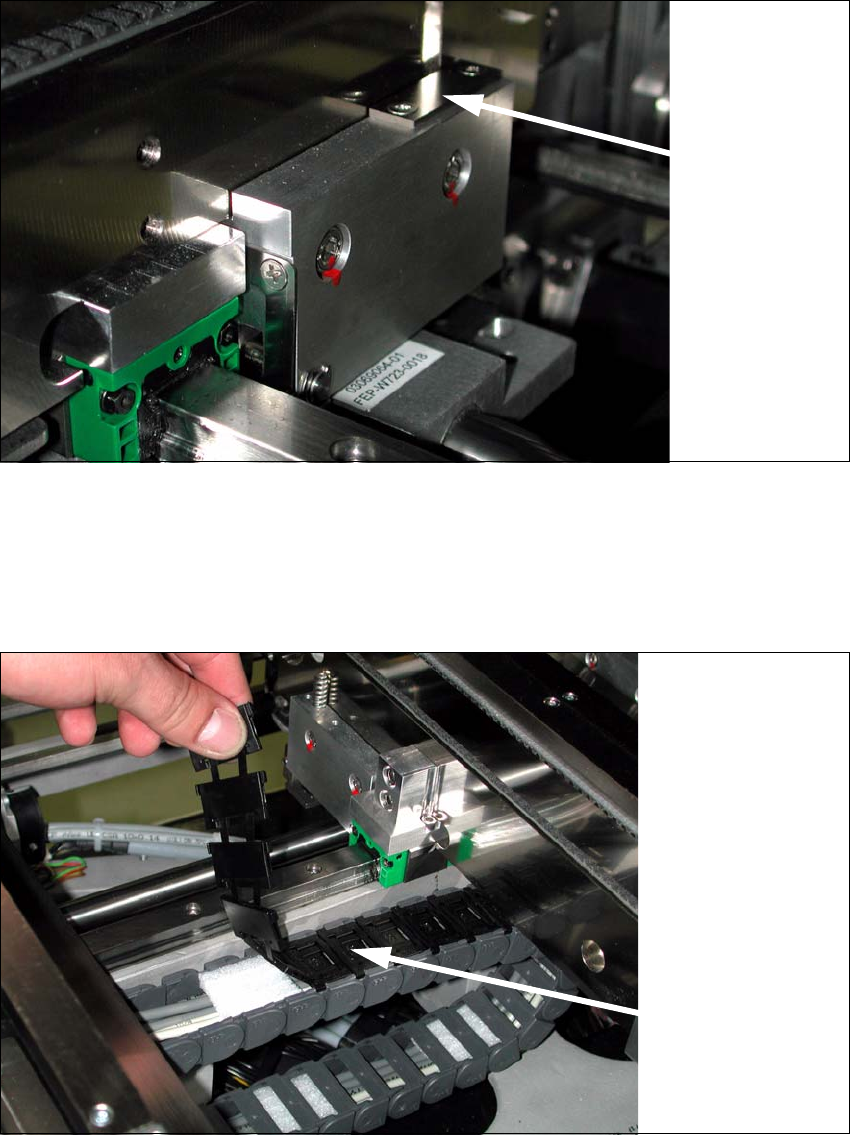
X Use a Phillips screwdriver to loosen the clamping fixtures for the conveyor sides.
2
X Dismantle the lifting table plate at conveyor lane 1.
X Remove the covers above the conveyor control.
X Open the trailing cable.
2
2
Loosen the
conveyor side
clamps 2
Trailing cable2