00196609-0102_ AI_Optional_Stopper_SX1_2_DE+EN.pdf - 第41页
Optional stopper 2 Assembly Instructions for Optional Stopper SIPLACE SX1/SX2 Edition 09/2009 41 X Fit the two approx. 500 mm long PUN3 hoses onto the stoppers and scre w the stoppers on to the sensor rail (screws M4x8 /…
2 Assembly Instructions for Optional Stopper SIPLACE SX1/SX2 Optional stopper
Edition 09/2009
40
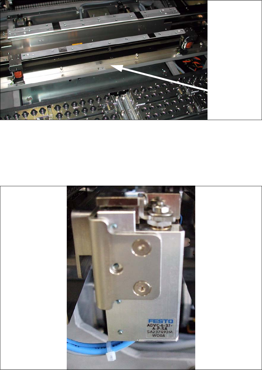
X Remove the metal angular bracket from the cable duct.
2
2.5.1 Fitting the Stopper on the Sensor Rail
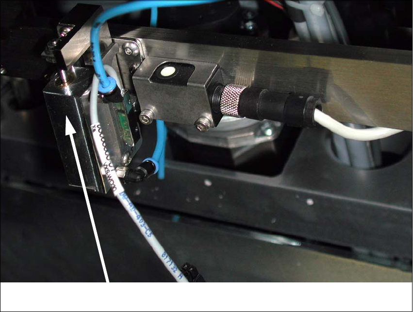
X Fit the stopper onto the retaining bracket (M3x8 / 7991 hexagonal socket-countersunk head),
in the bottom position (the two top screw holes on the bracket).
Cover on
cable duct
2
Optional stopper 2 Assembly Instructions for Optional Stopper SIPLACE SX1/SX2
Edition 09/2009
41
X Fit the two approx. 500 mm long PUN3 hoses onto the stoppers and screw the stoppers onto
the sensor rail (screws M4x8 / 7380 hexagon socket fillister head).
2
Stopper2
2 Assembly Instructions for Optional Stopper SIPLACE SX1/SX2 Optional stopper
Edition 09/2009
42
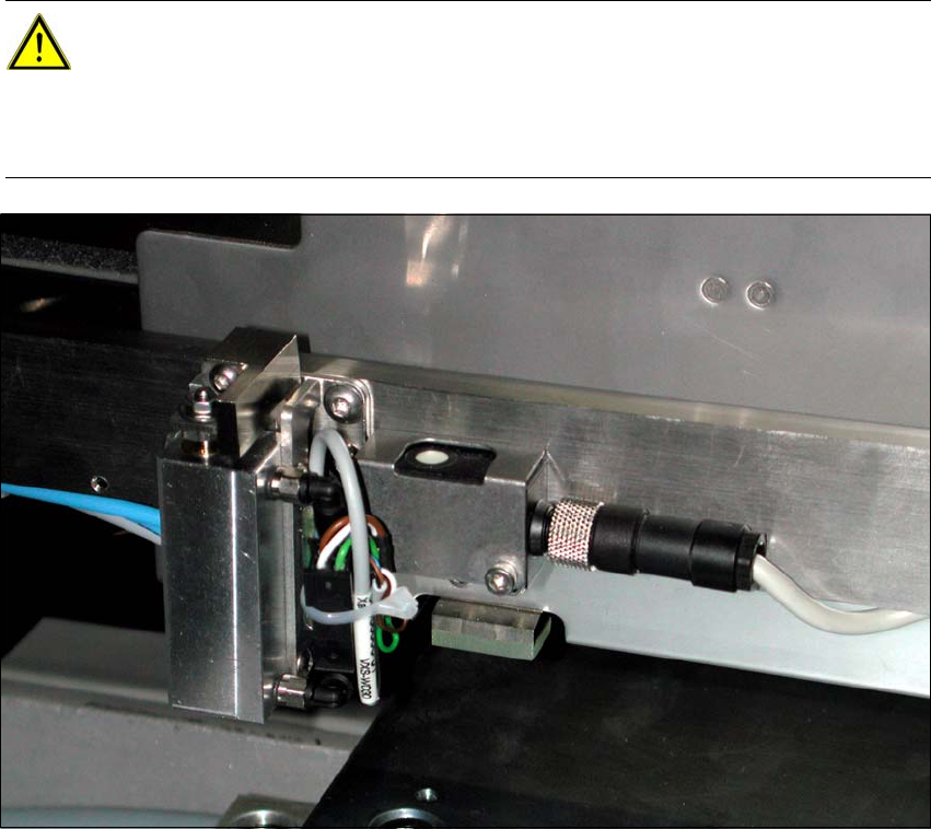
X Connect the cable to the stoppers. Loop the cable at the cable tie to create a strain relief.
X Fix the two hoses and cable to the adhesive base so that the sensor rail can be adjusted be-
tween 0 - 70 mm.
2
2
CAUTION:
Make sure that there are no folds in the hoses or other points where the hoses are
pinched in the adjustment range. Also make sure that the hose and cables are not routed
lower than the stopper in the placement area, otherwise the lifting table could catch and
pinch them. 2