00196609-0102_ AI_Optional_Stopper_SX1_2_DE+EN.pdf - 第44页
2 Assembly Instructions for Optional Stopper SIPLACE SX1/SX2 Optional stopper Edition 09/2009 44 X Fix into place by threading the cable ties through th e free screw holes in the side p anel or use the cable clamp s prov…
Optional stopper 2 Assembly Instructions for Optional Stopper SIPLACE SX1/SX2
Edition 09/2009
43
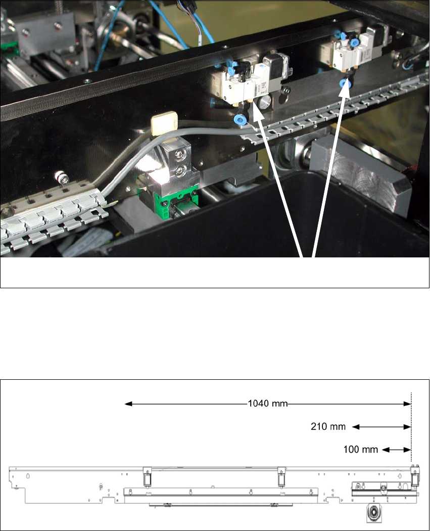
Fitting the solenoid valves on the conveyor side 2
X Use the fixture clamps and double-sided adhesive tape to fasten the valves to the conveyor
side.
2
Center valve input conveyor 1040 mm from stopper output conveyor 2
Center valve placement area 210 mm from stopper output conveyor 2
Center valve output conveyor 100 mm from stopper output conveyor 2
2
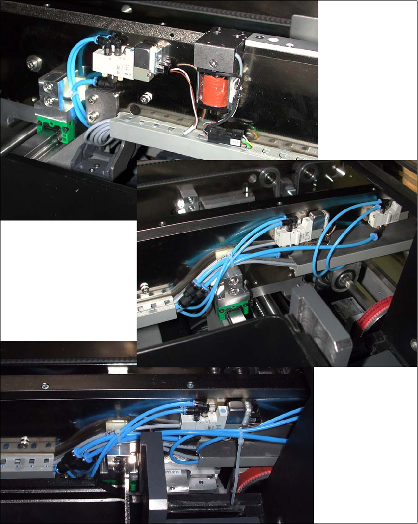
X Run the hoses from the stopper to the solenoid valves, so that these are not pinched at any
points.
Solenoid valves 2

2 Assembly Instructions for Optional Stopper SIPLACE SX1/SX2 Optional stopper
Edition 09/2009
44
X Fix into place by threading the cable ties through the free screw holes in the side panel or use
the cable clamps provided.
X Cut the hoses into the correct lengths and connect these to the solenoid valve.
X Connect the cable and the PUN4 hose to the solenoid valve.
2
NOTE:
Observe the pneumatic and circuit diagrams while performing this. 2
Optional stopper 2 Assembly Instructions for Optional Stopper SIPLACE SX1/SX2
Edition 09/2009
45
Running the option cable 2
X Fit the valve cable and pneumatic hoses incl. Y pieces. These are then run in the cable duct
and threaded through the power track chain.
X Connect the PUN 4 hoses in the mounting frame cable duct with the pneumatic supply line for
the conveyor.