00196609-0102_ AI_Optional_Stopper_SX1_2_DE+EN.pdf - 第43页
Optional stopper 2 Assembly Instructions for Optional Stopper SIPLACE SX1/SX2 Edition 09/2009 43 Fitting the solenoid valves on the convey or side 2 X Use the fixture clamp s and double-sided ad hesive tape to fasten the…
2 Assembly Instructions for Optional Stopper SIPLACE SX1/SX2 Optional stopper
Edition 09/2009
42
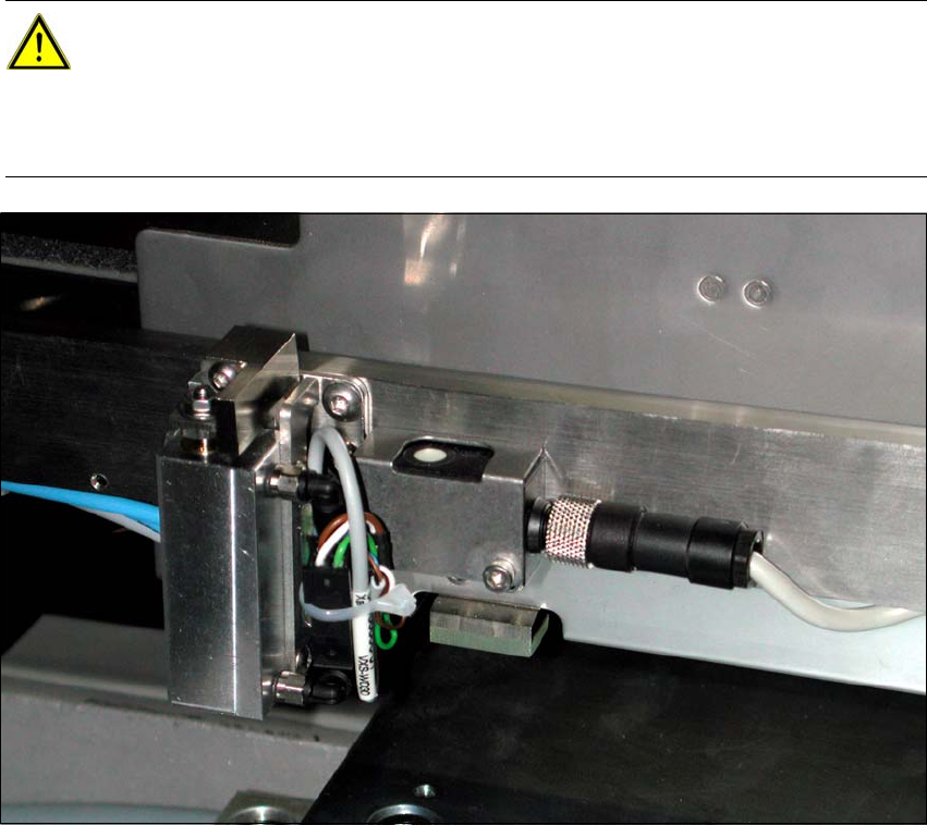
X Connect the cable to the stoppers. Loop the cable at the cable tie to create a strain relief.
X Fix the two hoses and cable to the adhesive base so that the sensor rail can be adjusted be-
tween 0 - 70 mm.
2
2
CAUTION:
Make sure that there are no folds in the hoses or other points where the hoses are
pinched in the adjustment range. Also make sure that the hose and cables are not routed
lower than the stopper in the placement area, otherwise the lifting table could catch and
pinch them. 2
Optional stopper 2 Assembly Instructions for Optional Stopper SIPLACE SX1/SX2
Edition 09/2009
43
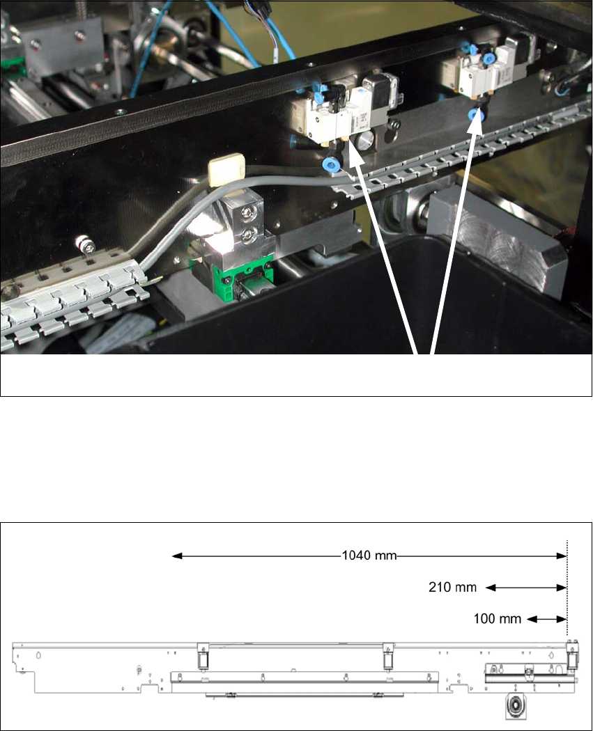
Fitting the solenoid valves on the conveyor side 2
X Use the fixture clamps and double-sided adhesive tape to fasten the valves to the conveyor
side.
2
Center valve input conveyor 1040 mm from stopper output conveyor 2
Center valve placement area 210 mm from stopper output conveyor 2
Center valve output conveyor 100 mm from stopper output conveyor 2
2
X Run the hoses from the stopper to the solenoid valves, so that these are not pinched at any
points.
Solenoid valves 2

2 Assembly Instructions for Optional Stopper SIPLACE SX1/SX2 Optional stopper
Edition 09/2009
44
X Fix into place by threading the cable ties through the free screw holes in the side panel or use
the cable clamps provided.
X Cut the hoses into the correct lengths and connect these to the solenoid valve.
X Connect the cable and the PUN4 hose to the solenoid valve.
2
NOTE:
Observe the pneumatic and circuit diagrams while performing this. 2