00195089-0102_AI_Vakuumpumpe_X-Serie_60X_DE+EN.pdf - 第107页
Assembly Instructions SIPLACE Vacuum Pump Ausgabe 07/2006 103 Fig. 2.10.2 Open vacuum pump (1) Factory-adjusted pressure limit valve (2) Air filter (3) Control connectors for 4 placement machine s 2 : Fasten the vacuum h…
Assembly Instructions SIPLACE Vacuum Pump
Ausgabe 07/2006
102
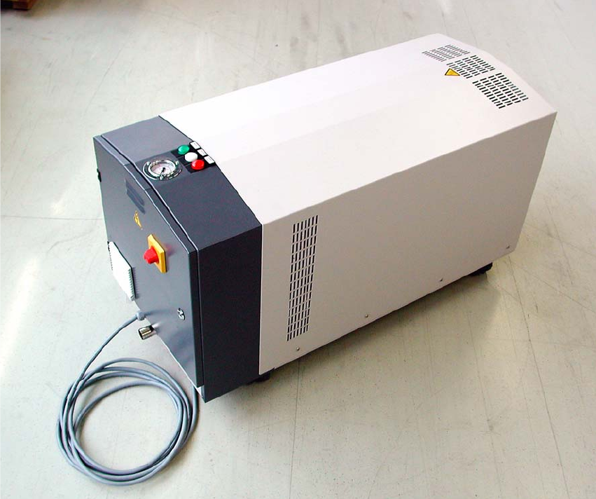
Fig. 2.10.1 Vacuum pump with pressure gauge, control lamp, main switch, power cable and vacuum connection.
Assembly Instructions SIPLACE Vacuum Pump
Ausgabe 07/2006
103
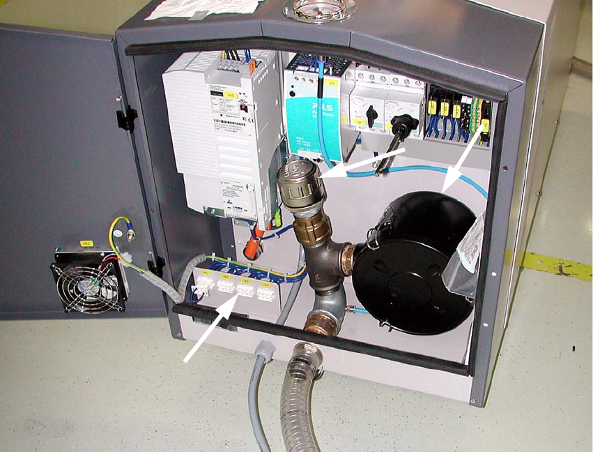
Fig. 2.10.2 Open vacuum pump
(1) Factory-adjusted pressure limit valve
(2) Air filter
(3) Control connectors for 4 placement machines
2
: Fasten the vacuum hose (siphon and pressure hose) with a hose clamp.
: Trim the vacuum pump with a knife or wire cutter, based on your set-up.
: Secure the Y connector on the other end.
: Run one vacuum hose each to the individual placement machines.
Assembly Instructions SIPLACE Vacuum Pump
Ausgabe 07/2006
104
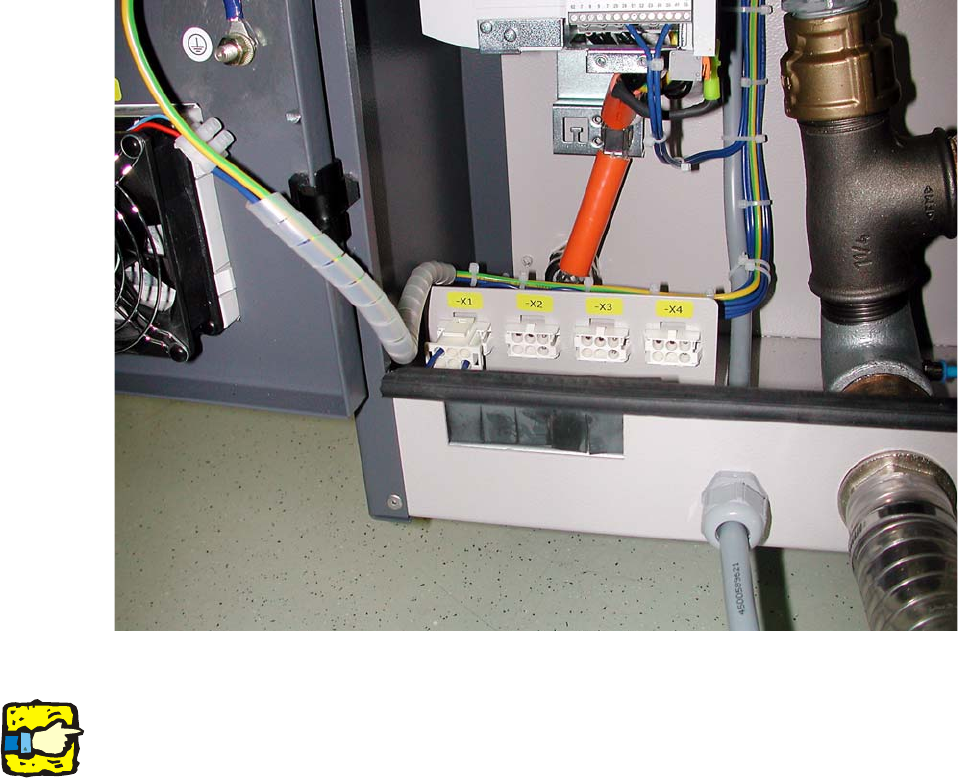
Fig. 2.10.3 Control connectors for Portals X1 through X4
2
Monitoring and/or control of the vacuum pump is available at the earliest starting with SW version
603.
If you would like to control the vacuum pump using the con
nected placement machine’s operating
state: 2
: Remove the strapping plug.
: Guide the control cable “cable power vacuum pump” (03049005-) through the opening below
the door.
: Plug in the control cables of each placement machine accordingly (X1 through X4).
: Plug the other ends into the plug X16 in the bottom distributor of each connected placement
machine (see Fig. 2.9.3).