00195089-0102_AI_Vakuumpumpe_X-Serie_60X_DE+EN.pdf - 第99页
Assembly Instructions SIPLACE Vacuum Pump Ausgabe 07/2006 95 Fig. 2.9.3 Plug X16 for the v acuum pump’ s control cable : Secure plug X16 as shown in Fig. 2.9.3. 2
Assembly Instructions SIPLACE Vacuum Pump
Ausgabe 07/2006
94
2.9.2 Mounting
2
Before any work is performed the machine – after being properly shut down – must be turned off
at the main switch and separated from the power system. Thereafter the compressed air supply
must be also turned off at the compressed air unit’s main valve in the machine stand. The air
supply must then be ventilated by activating the needle valve on the compressed air unit. Please
also follow the safety instructions in Chapter 2.5.
: En
sure that the placement machine is turned off and removed from the power system.
: Unsc
rew the bottom distributor’s steel flooring.
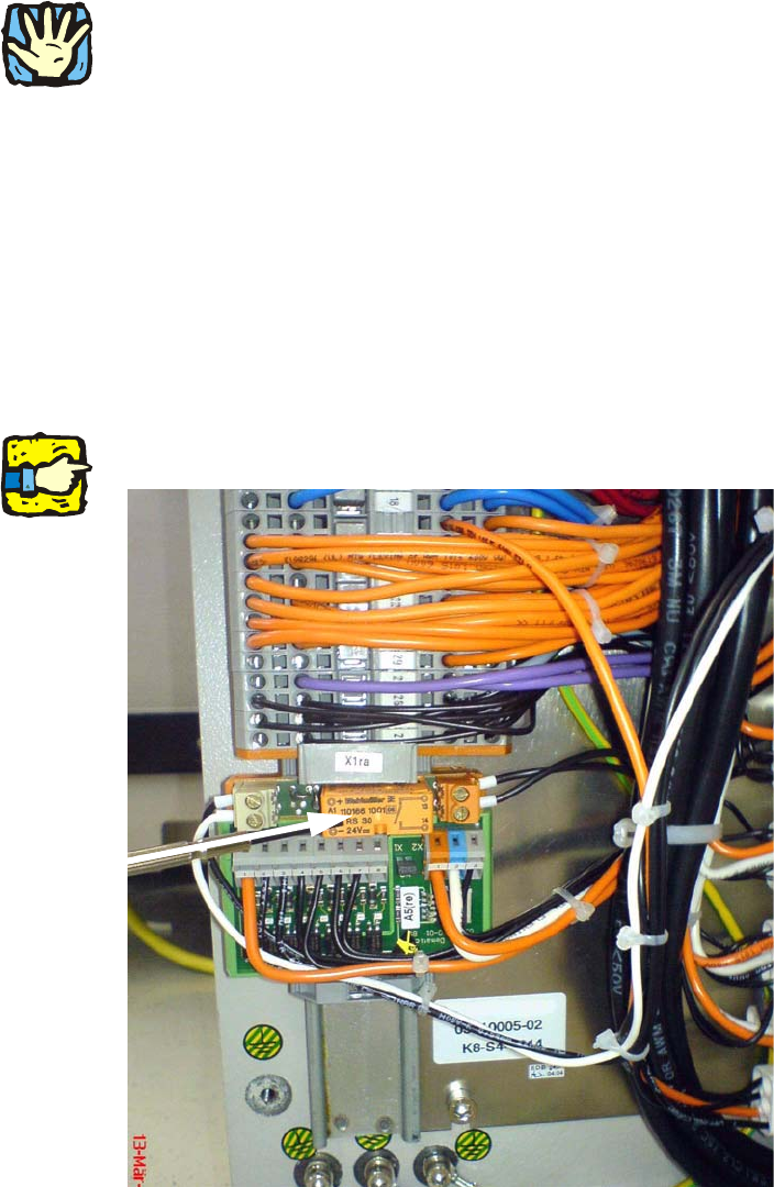
: Push the "Plate 8 times UND connector" slightly down so that there is room above it.
: Press the relay K2 (03048999-) in the now open space onto the top hat rail until it clicks in (see
Fig. 2.9.2).
2
This relay has already been cabled with plugs and wire ends for further installation. 2
Fig. 2.9.2 Relay fitted
2
Assembly Instructions SIPLACE Vacuum Pump
Ausgabe 07/2006
96
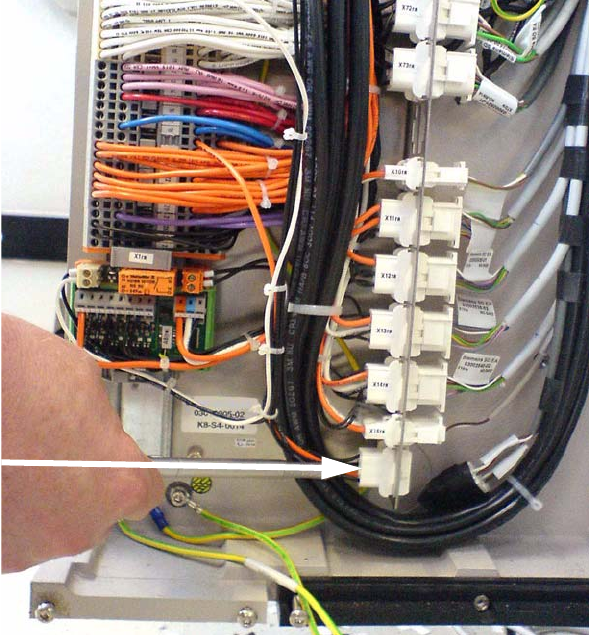
Fig. 2.9.4 Eingang DI6
: Wire the black cable from X16 ra_2 to input DI6 on the “CAN In/Out module 2” (see Fig. 2.9.4 ).
2
Don’t mix up the cables! 2
2
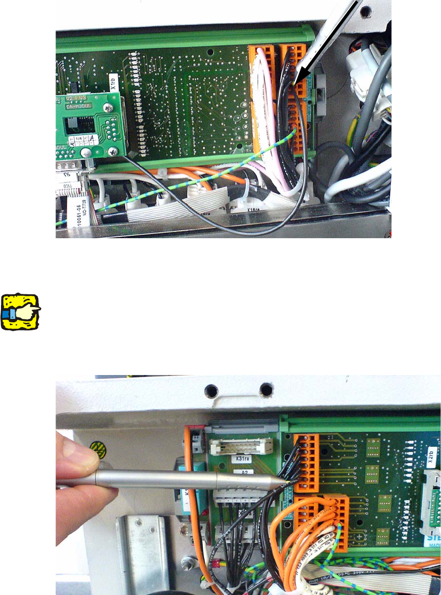
: Wire the black cable from relay K2_A1 to output DO6 on the “CAN In/Out module 2” (see Fig.
2.9.5).
Fig. 2.9.5 Output DO6