00195089-0102_AI_Vakuumpumpe_X-Serie_60X_DE+EN.pdf - 第118页
Assembly Instructions SIPLACE Vacuum Pump Ausgabe 07/2006 114 Abb . 2.12.2 Connections C&P12 with compre ssed air operation (star ting position) : Replace the old vacuum g enerator with the “vacuum gen erator for vac…
Assembly Instructions SIPLACE Vacuum Pump
Ausgabe 07/2006
113
2.12 Retrofitting C&P12 and C&P6
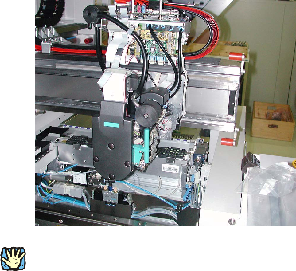
Abb. 2.12.1 C&P12 with compressed air (starting position)
2
Before any work is performed the machine – after being properly shut down – must be turned off
at the main switch and separated from the power system. Thereafter the compressed air supply
must also be turned off at the compressed air unit’s main valve in the machine stand. The air
supply must then be ventilated by activating the needle valve on the compressed air unit.
Assembly Instructions SIPLACE Vacuum Pump
Ausgabe 07/2006
114
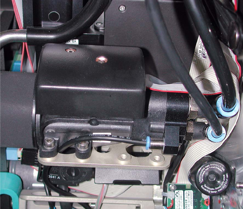
Abb. 2.12.2 Connections C&P12 with compressed air operation (starting position)
: Replace the old vacuum generator with the “vacuum generator for vacuum pump DLM2”
(03012076-)

Assembly Instructions SIPLACE Vacuum Pump
Ausgabe 07/2006
115
2.13 Technical Information
About Retrofitting for Vacuum Pump Operation
2.13.1 General Information About Vacuum Pump Operation
Mutual interference of multiple placement machines at a joint pump: 2
If multiple placement machines are connected to one vacuum p
ump, it is advisable to insert an
additional shut-off valve into the vacuum input before each placement machine. 2
2
2
During normal operation the vacuum in the vacuum distributor block at the machine input should
not fall below -500mbar. 2
2
To avoid any possible property damage despite this measure, the placement machines should not
be turned off if the vacuum pump is running. 2
2.13.2 Special Features of the C&P20 Placement Head
One vacuum pump can supply a maximum of 4 x C&P20 heads.
Example: 1x SIPLACE X4 with 4x C&P 20 o
r 2x SIPLACE X2 with 2x C&P 20 each 2
If the vacuum pump option is retrofitted, the Venturi vacu
um generator (“vacuum unit holding circle
C&P20") is replaced by the “orifice ring complete C&P20” (03046348-). Only the holding circle is
directly supplied by the vacuum pump. 2
In the collect and/or place position the pressure regulation
valve, as well as the return cylinder,
continue to be supplied with compressed air, independent from the holding circle. 2
The placement machine’s “vacuum usage” depends only on th
e number of placement heads and
the size of the pipettes. The more C&P20 heads are connected to the vacuum pump, the lower
the vacuum at the pipettes. 2
When starting placement operation the vacuum increases with each c
omponent picked up. A
median vacuum amount is quickly reached when pipettes are closed (components picked up) and
opened (components deposited) at the same time. 2
With an X4 during continuous placement operation, 2 of 4 heads are always closed by
component
s. 2