00195089-0102_AI_Vakuumpumpe_X-Serie_60X_DE+EN.pdf - 第93页
Assembly Instructions SIPLACE Vacuum Pump Ausgabe 07/2006 89 Fig. 2.8.9 Laying of v acuum hose Portal 1+3 : Secure the “connector dual hose ” (03038107- ) with M3x16mm screws (see Fig. 2.8.9). : Lay the two “dual hoses” …
Assembly Instructions SIPLACE Vacuum Pump
Ausgabe 07/2006
89
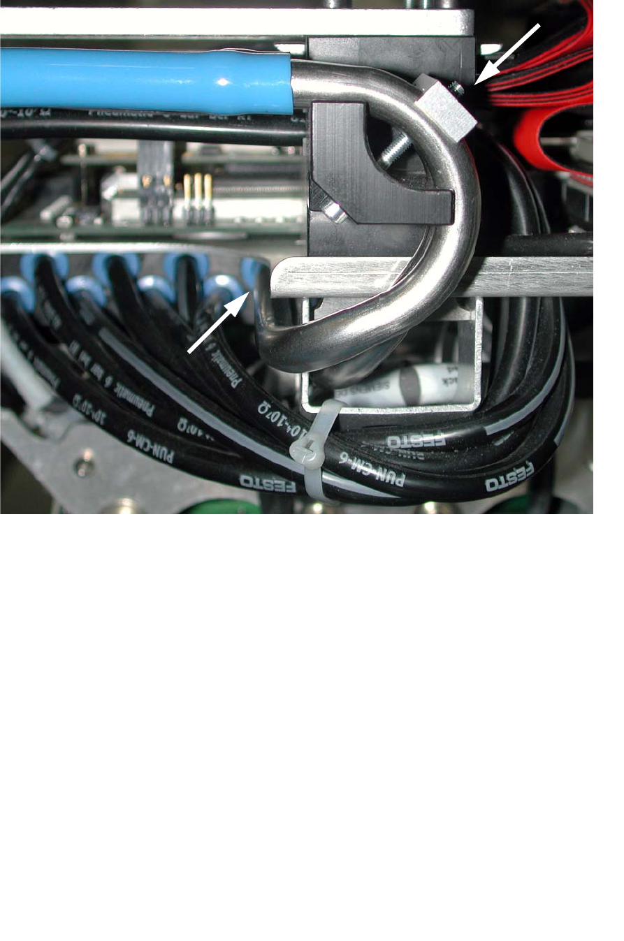
Fig. 2.8.9 Laying of vacuum hose Portal 1+3
: Secure the “connector dual hose” (03038107-) with M3x16mm screws (see Fig. 2.8.9).
: Lay the two “dual hoses” (two-tone) parallel to the existing cable drag chain.
: Secure the hoses (two-tone) at the “connector dual hose”.
Assembly Instructions SIPLACE Vacuum Pump
Ausgabe 07/2006
90
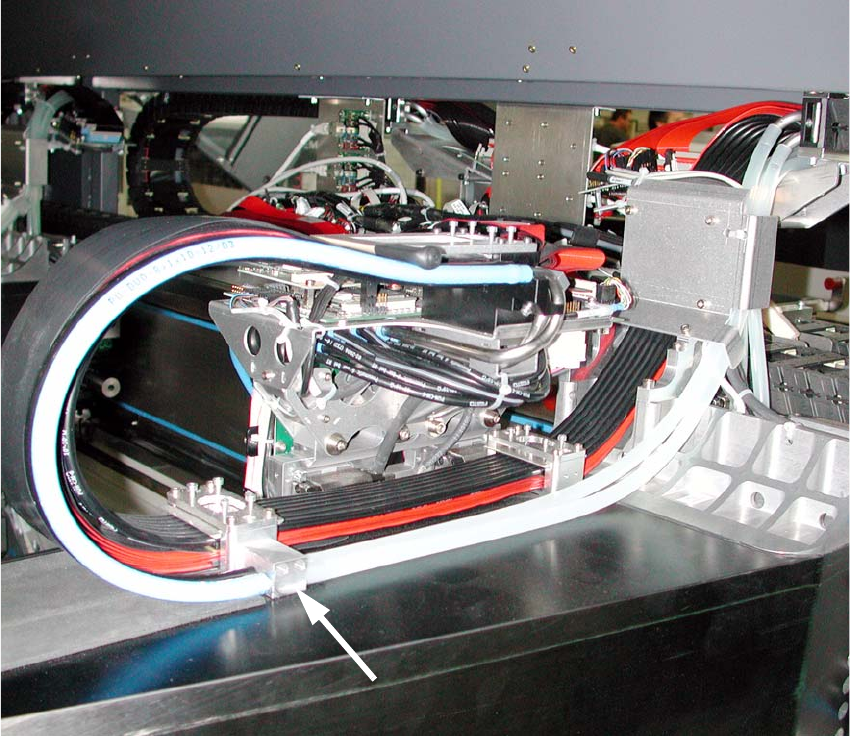
Fig. 2.8.10 Laying vacuum hose Portal 1+3
: Guide the (transparent) hoses up beneath the folding plate (see Fig. 2.8.10).
2
Different variations of the portal cable drag chain can cause differences here. If necessary, secure
the hoses to the existing cables with cable ties (see Fig. 2.8.3). 2
2
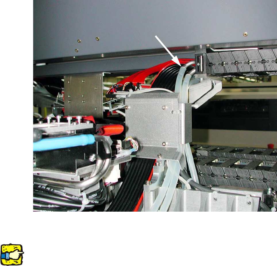
: Trim the transparent hoses.
: Plug the (transparent) hoses into the “connector dual hoses” and into the connection piece of
the cable drag chain (see Fig. 2.8.10 and Fig. 2.8.11).