00195089-0102_AI_Vakuumpumpe_X-Serie_60X_DE+EN.pdf - 第111页
Assembly Instructions SIPLACE Vacuum Pump Ausgabe 07/2006 107 2.1 1 Retrofitting C&P20 2 The T win Head is not comp atible with vacuum pumps. The pneumatic supply fo r a given portal must not be converted to vacuum o…
Assembly Instructions SIPLACE Vacuum Pump
Ausgabe 07/2006
106
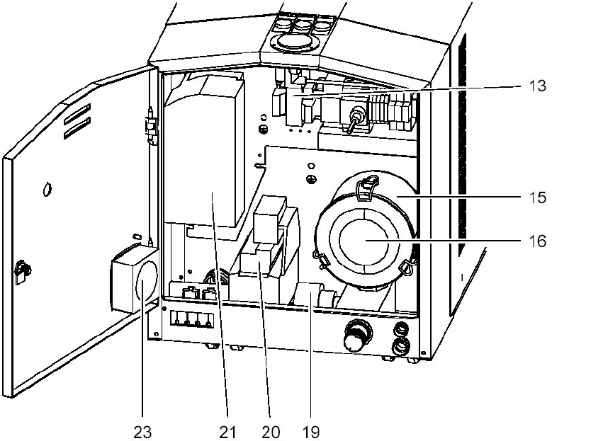
2.10.2 Spare Parts Vacuum Pump
Fig. 2.10.5 Spare parts vacuum pump
Description Item no. 2
1 pc Power choke for frequency converter 200V 03051646- 2
1 pc Frequency converter, external, 7,5kW, 200V 03051645- 2
1 pc Frequency converter, external, 7,5kW, 400V 03051644- 2
1 pc Air cooling unit for E-module 03051643- 2
1 pc Filter 03051642- 2
1 pc Valve 03051641- 2
1 pc Spare filter cartridge 03051640- 2
2
Spare Part Kit Vacuum Pump 2SH7530 00171131-01 2
1 pc Filter 03051642- 2
1 pc Valve 03051641- 2
1 pc Spare filter cartridge 03051640- 2
2

Assembly Instructions SIPLACE Vacuum Pump
Ausgabe 07/2006
107
2.11 Retrofitting C&P20
2
The Twin Head is not compatible with vacuum pumps. The pneumatic supply for a given portal
must not be converted to vacuum operation. If the compressed air supply for that head is
converted to vacuum operation, the return cylinder cannot extend and thus the z axis is stuck in
the top position. 2
2
If a portal is converted from Collect&Place to Twin Head, the original compressed air supply for
this portal must be reconstructed. All components for this portal must be reconstructed.
A partial conversion, e.g., of the pneumatic unit, can lead to severe failures in the placement
machine
when used in compressed air operation because the portal tubes (additional vacuum
tubes) can disconnect. 2
2
If a portal with Twin Head is converted to Collect&Place vacuum operation, the vacuum operation
for that portal must be retrofitted.
If a Collect&Place head which was converted to vacuum o
peration is operated at a compressed
air portal, the head could be severely damaged because the silicon tubes could disconnect. 2
2
Assembly Instructions SIPLACE Vacuum Pump
Ausgabe 07/2006
108
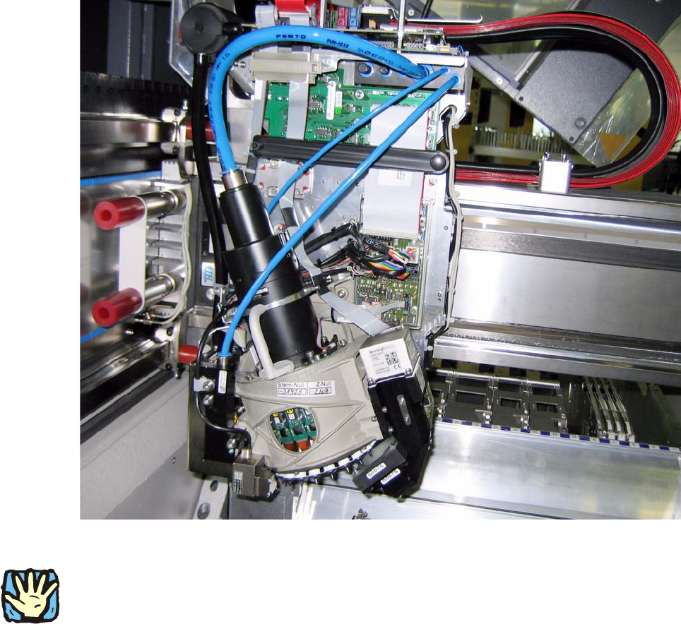
Fig. 2.11.1 C&P20, fitted with hoses for compressed air (starting position)
2
Before any work is performed the machine – after being properly shut down – must be turned off
at the main switch and separated from the power system. Thereafter the compressed air supply
must also be turned off at the compressed air unit’s main valve in the machine stand. The air
supply must then be ventilated by activating the needle valve on the compressed air unit.
.