00195089-0102_AI_Vakuumpumpe_X-Serie_60X_DE+EN.pdf - 第92页
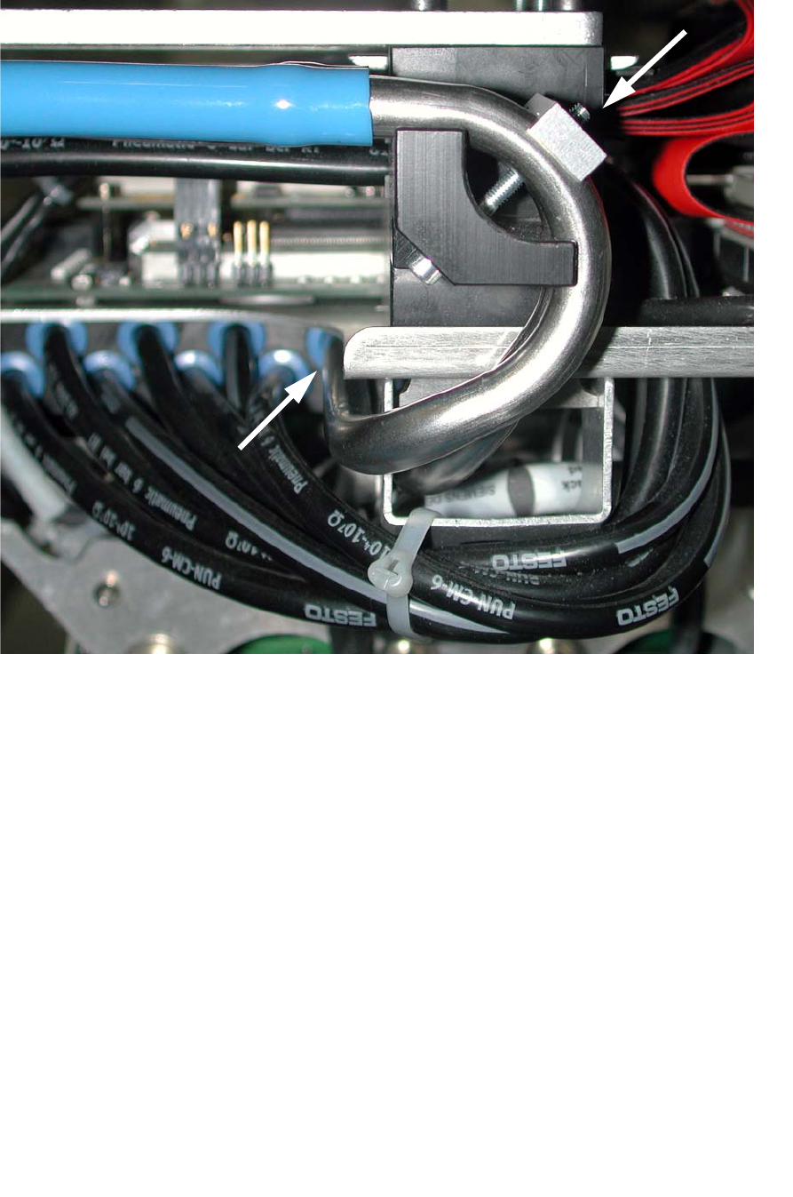
Assembly Instructions SIPLACE Vacuum Pump Ausgabe 07/2006 88 Fig. 2.8.8 Gooseneck plugged in and fix ed into position : Secure the vacuum pip es “vacuum connection 1+ 2” with the clamp ing device (03032860-), a M3x30mm s…
Assembly Instructions SIPLACE Vacuum Pump
Ausgabe 07/2006
87
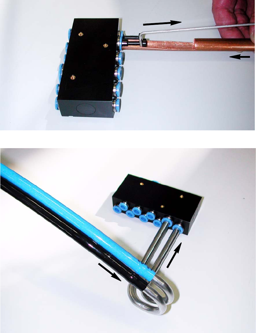
Fig. 2.8.6 Release tool for connections which are difficult to reach
Fig. 2.8.7 Distributor placement head (removed to better depict it)
: Plug the vacuum hoses into the vacuum pipes “vacuum connection 1 +2” as shown in Fig.
2.8.7.
: Plug the two pipes into the “distributor placement head vacuum” (Fig. 2.8.7).
Assembly Instructions SIPLACE Vacuum Pump
Ausgabe 07/2006
89
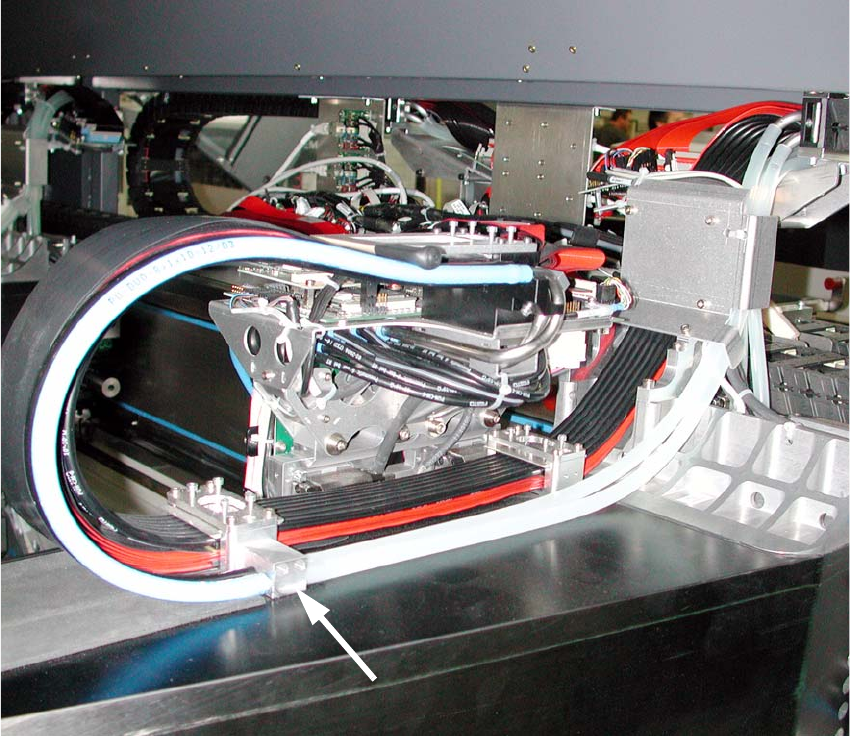
Fig. 2.8.9 Laying of vacuum hose Portal 1+3
: Secure the “connector dual hose” (03038107-) with M3x16mm screws (see Fig. 2.8.9).
: Lay the two “dual hoses” (two-tone) parallel to the existing cable drag chain.
: Secure the hoses (two-tone) at the “connector dual hose”.