00195089-0102_AI_Vakuumpumpe_X-Serie_60X_DE+EN.pdf - 第124页
Assembly Instructions SIPLACE Vacuum Pump Ausgabe 07/2006 120 2 The change in the machine dat a base can only be made by SIPLACE service. 2 2 2 : Select the table "vacuu m/bubble air paramete rs” in the dat abase (s…

Assembly Instructions SIPLACE Vacuum Pump
Ausgabe 07/2006
119
Procedure to Inspect Leak Tightness for C&P20 Head: 2
2
To prevent differences based on offset errors, it makes sense to take both measurements with the
same measuring device. 2
2
: Measure the vacuum with the external pressure measurement device:
– at an attachment of the “distributor placement head vacuum” at the portal (see Fig. 2.8.5)
and thereafter
– at an open pipette in the placement head’s holding circle.
The pressure differential can be a max. of 30-5
0 mbar
! Otherwise not everything is leak tight. 2
2
Measurements during the vacuum test (in the SITEST) always occur with an open pipette. For
large pipettes (1235) the vacuum is generally lowered to below -100 mbar because of a higher
amount of absent air. The reason for this high slump – for large pipettes without component – is
the relatively small reduction jet diameters in the orifice ring compared to the pipette diameter.
With a component, vacuum values of -500 to -600 mbar are reached. 2
If these values are not reached, the reason is usually
a hose in the head area which is not pulled
up all the way to the catch. Do the following: 2
: Re-squeeze all hoses with the tube gripper.
: Repeat th
e vacuum measurement.
2.14.2.2 Inspect Entire Function of the C&P20’s Holding Circle Vacuum System
The entire function of the vacuum system can be tested by a vacuum test in the SITEST, just like
with the Venturi principle. 2
The vacuum sensor in the holding circle is only used to
check whether the small jets in the orifice
ring are free of dirt. 2
2.14.2.3 Inspect C&P6/12’s Holding Circle Vacuum System for Leak Tightness
If a vacuum pump for the X Series (C&P20) is used, the following differences with the vacuum
pump for the HS-60/HF occur: 2
– Throughput is 4x higher than for the “vacuum pump fo
r HS-xx/S-27HM/HF” (item no. 119017)
– The maximum vacuum reached now is at approx. -640 mbar, instead of the previous -850
mbar.
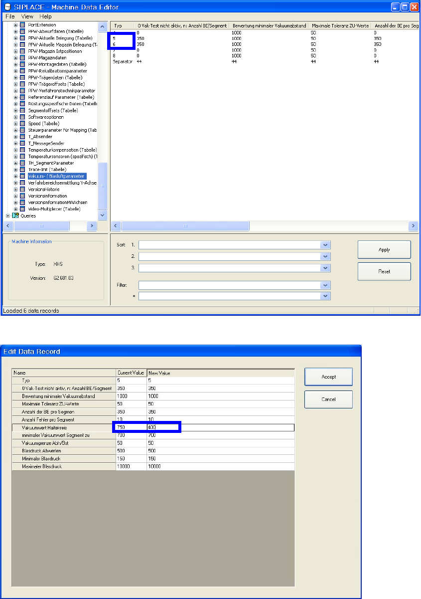
Therefore the minimally allowable vacuum value for the holding circle must be reduced
from -750 to -400 mbar. Otherwise an error message “258 vacuum in holding circle too low
(should/is)” occurs during the reference run.

Assembly Instructions SIPLACE Vacuum Pump
Ausgabe 07/2006
120
2
The change in the machine data base can only be made by SIPLACE service. 2
2
2
: Select the table "vacuum/bubble air parameters” in the database (see Fig. 2.14.2).
: Wechseln Sie für die Kopftypen 5 und 6 jeweils in den Editiermodus.
: Change the “vacuum value holding circle” from 750 to 400 (see Fig. 2.14.3).
2
2
During a SW update or when using an MC distributor this data is overwritten. It must be edited
again thereafter! 2
Assembly Instructions SIPLACE Vacuum Pump
Ausgabe 07/2006
121
Fig. 2.14.2 Select table vacuum/bubble air parameters
Fig. 2.14.3 Correct vacuum values holding circle