00195089-0102_AI_Vakuumpumpe_X-Serie_60X_DE+EN.pdf - 第80页
Assembly Instructions SIPLACE Vacuum Pump Ausgabe 07/2006 76 Fig. 2.7.5 Hose labelling (here for P or tal 3+4) Fig. 2.7.6 Retrofitted pneumatic distri butor f or Portal 1+2 (facing side) : Plug the hoses into the portal …
Assembly Instructions SIPLACE Vacuum Pump
Ausgabe 07/2006
75
Depending on the portal configuration, the following dummy plugs must be removed: 2
2
A portal with Twin Head cannot be retrofitted. Leave the dummy plug for the corresponding portal
in the distributor. 2
2
– X2: Plug for Portal 1 (power supply side) and Portal 3 (pneumatics side)
– X3: Plug for Portal 1 + 2 (power supply side) und Portal 3 (pneumatics side)
– X4: Plug for Portal 1 + 2 (power supply side) und Portal 3 + 4 (pneumatics side)
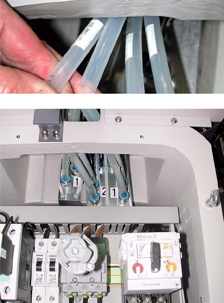
: To do so, press the blue rings (see Fig. 2.7.3) in th
e dir
ection of the axis and remove the cor-
responding dummy plug.
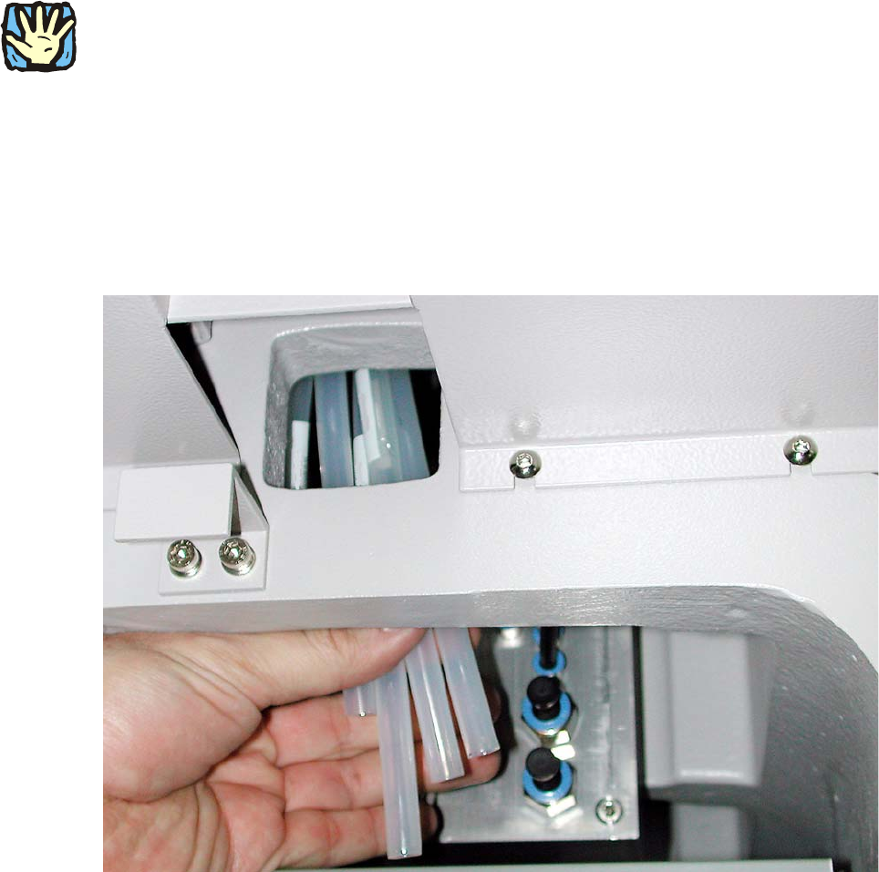
Fig. 2.7.4 Hoses run at manufacturer’s (here for Portal 1+2)
: Pull the hoses down until you can see the labelling.
Assembly Instructions SIPLACE Vacuum Pump
Ausgabe 07/2006
76
Fig. 2.7.5 Hose labelling (here for Portal 3+4)
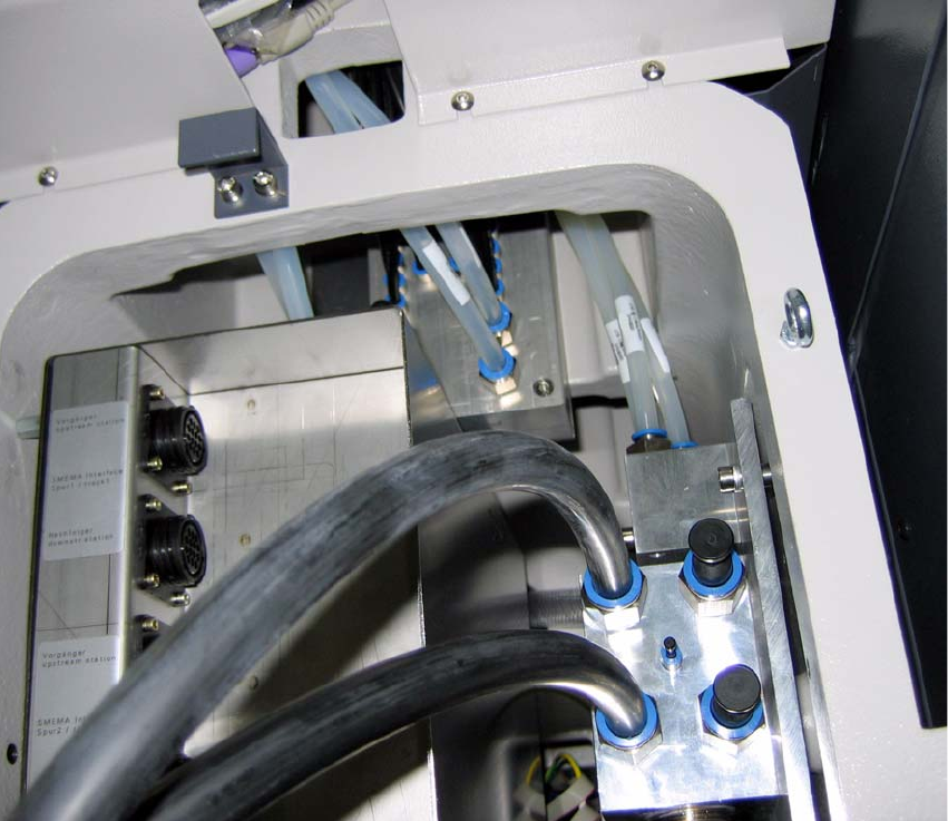
Fig. 2.7.6 Retrofitted pneumatic distributor for Portal 1+2 (facing side)
: Plug the hoses into the portal distributor, based on the labelling and the machine configuration
(both for Portal 1+2 and Portal 3+4).
Assembly Instructions SIPLACE Vacuum Pump
Ausgabe 07/2006
77
2.7.2 Retrofitting the Pneumatic Unit and
Connecting the Vacuum Distributor Block
Fig. 2.7.7 Fasten vacuum distributor block
: Fasten the vacuum distributor block to the plate with the two screws (00845068-, DIN912,
M6x70-8.8).
2