00195089-0102_AI_Vakuumpumpe_X-Serie_60X_DE+EN.pdf - 第94页
Assembly Instructions SIPLACE Vacuum Pump Ausgabe 07/2006 90 Fig. 2.8.10 Laying v acuum hose Portal 1+3 : Guide the (transp arent) hoses up beneat h the folding plate (see Fig . 2.8.10). 2 Diff erent variations of the po…
Assembly Instructions SIPLACE Vacuum Pump
Ausgabe 07/2006
89
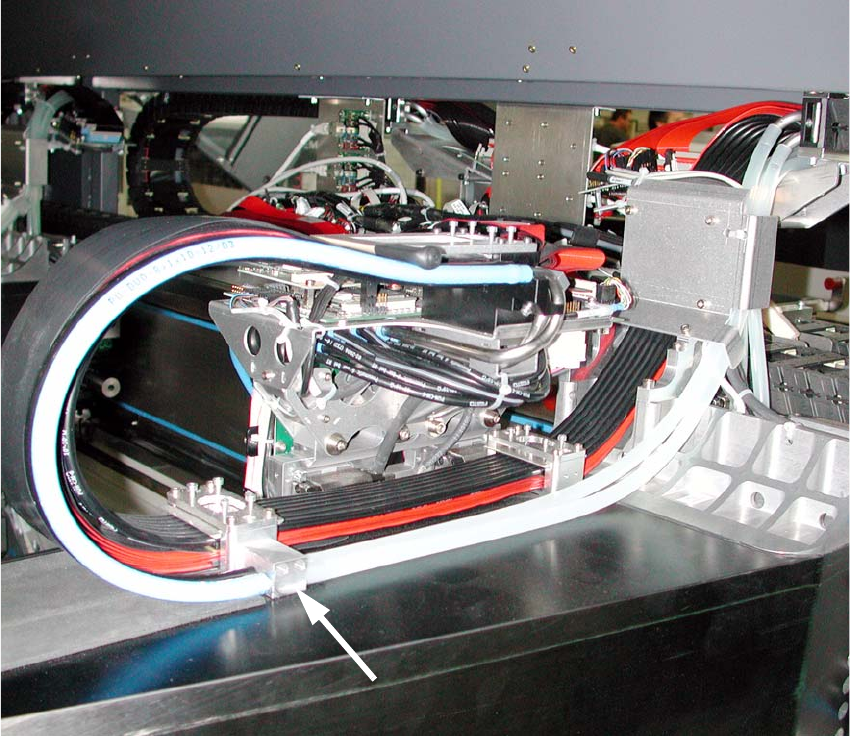
Fig. 2.8.9 Laying of vacuum hose Portal 1+3
: Secure the “connector dual hose” (03038107-) with M3x16mm screws (see Fig. 2.8.9).
: Lay the two “dual hoses” (two-tone) parallel to the existing cable drag chain.
: Secure the hoses (two-tone) at the “connector dual hose”.
Assembly Instructions SIPLACE Vacuum Pump
Ausgabe 07/2006
90
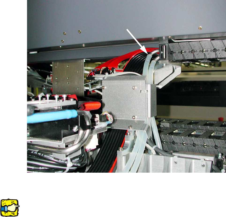
Fig. 2.8.10 Laying vacuum hose Portal 1+3
: Guide the (transparent) hoses up beneath the folding plate (see Fig. 2.8.10).
2
Different variations of the portal cable drag chain can cause differences here. If necessary, secure
the hoses to the existing cables with cable ties (see Fig. 2.8.3). 2
2
: Trim the transparent hoses.
: Plug the (transparent) hoses into the “connector dual hoses” and into the connection piece of
the cable drag chain (see Fig. 2.8.10 and Fig. 2.8.11).
Assembly Instructions SIPLACE Vacuum Pump
Ausgabe 07/2006
91
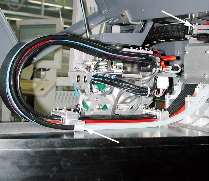
Fig. 2.8.11 Laying of vacuum hose Portal 2+4