3OM-1054-002.pdf - 第237页
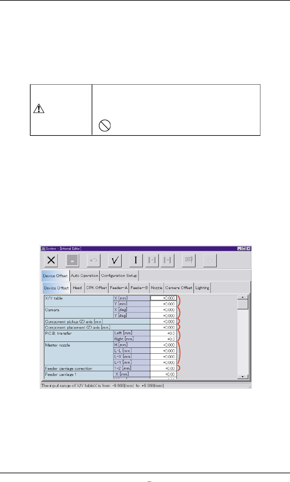
Fig. 3E1 1-1 Fig. 3E1 1-2 0307-002 5-11-1 AGS01EDTP 3.2 "Device Offset" T ab *9 *8 *10 *1 1 *12 *13 *14
3.2 "Device Offset" Tab
This session describes how to set various kinds of offset data for each
device position adjustment related to machine operation, for the cam-
era system related to placement accuracy, for the heads, and for the
nozzles.
CAUTION
Do not change the parameters unless necessary.
These parameters are factory-adjusted upon shipment
of the machine.
• Some parameters are automatically calculated through teaching op-
erations.
3.2.1 "Device Offset" Tab
• Sheet Layout
When the "Device Offset" tab is pressed in the "Device Offset" tab sheet,
the following tab sheet appears.
Fig. 3E11 "Device Offset" Tab Sheet
0303-005 5-11 AGS01EDTP
3.2 "Device Offset" Tab
*1
*2
*5
*3
*4
*7
*6
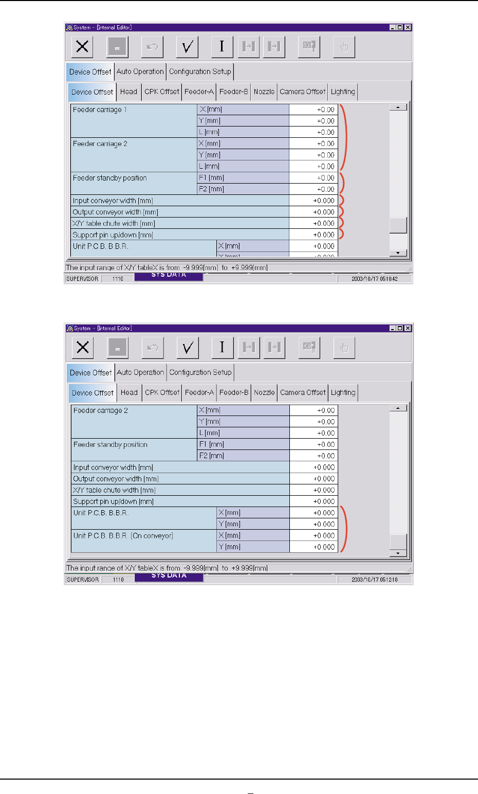
Fig. 3E11-1
Fig. 3E11-2
0307-002 5-11-1 AGS01EDTP
3.2 "Device Offset" Tab
*9
*8
*10
*11
*12
*13
*14
• Sheet Composition
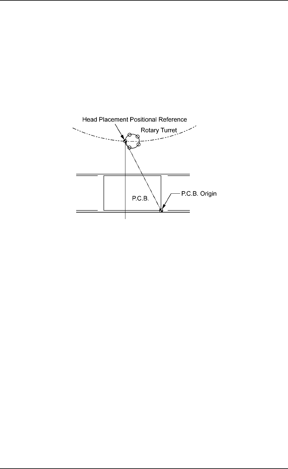
*1 X/Y table X [mm] (Horizontal), Y [mm] (Vertical)
This is the offset data between the X/Y table origin and the positional
reference of the head’s component placement.
When the X/Y table is at its origin, the distance between the P.C.B.
origin and the positional reference (reference head position) for com-
ponent placement performed by a nozzle on the No. 1 head should
be set to adjust the data compared with the design values.
Fig. 3E12
0307-005 5-12
AGS01EDTP
3.2 "Device Offset" Tab