3OM-1054-002.pdf - 第241页
Plus parameters entered in these text boxes increase the travel of the feeder carriages in the "Fdr . No." direction from the component pickup position. Fig. 3E15 *9 Feeder standby position F1 [mm], F2 [mm] Sho…
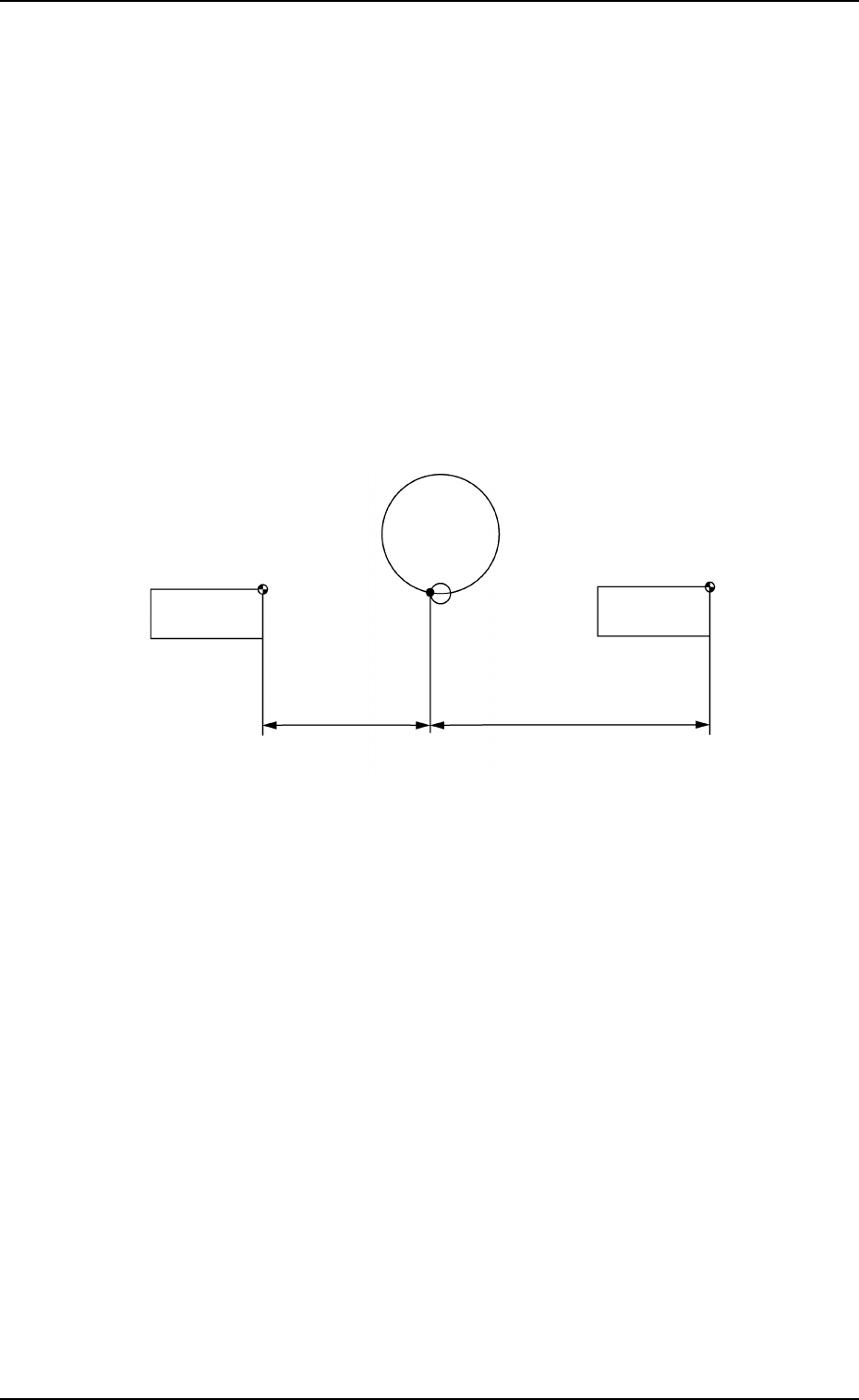
*7 Feeder carriage connection 1-2 [mm]
This is the offset data used to adjust the space between the two
feeder carriages when connected.
Reserved Data
*8 Feeder carriage 1 X (Horizontal) [mm], Y (Vertical) [mm], L
(Height) [mm], 2 X (Horizontal) [mm], Y (Vertical) [mm], L (Height)
[mm]
This is the offset data used to adjust the positional distances be-
tween the component pickup position and the feeder carriages.
X [mm] (Horizontal) : Horizontal Position Data
Y [mm] (Vertical) : Vertical Position Data
L [mm] (Height) : Pickup Height Position Data
Fig. 3E14
0307-005 5-14
AGS01EDTP
3.2 "Device Offset" Tab
Pickup
Position
Feeder Carriage #2
FDR. 201 at Origin
Feeder Carriage #1
FDR. 101 at Origin
#2
#1
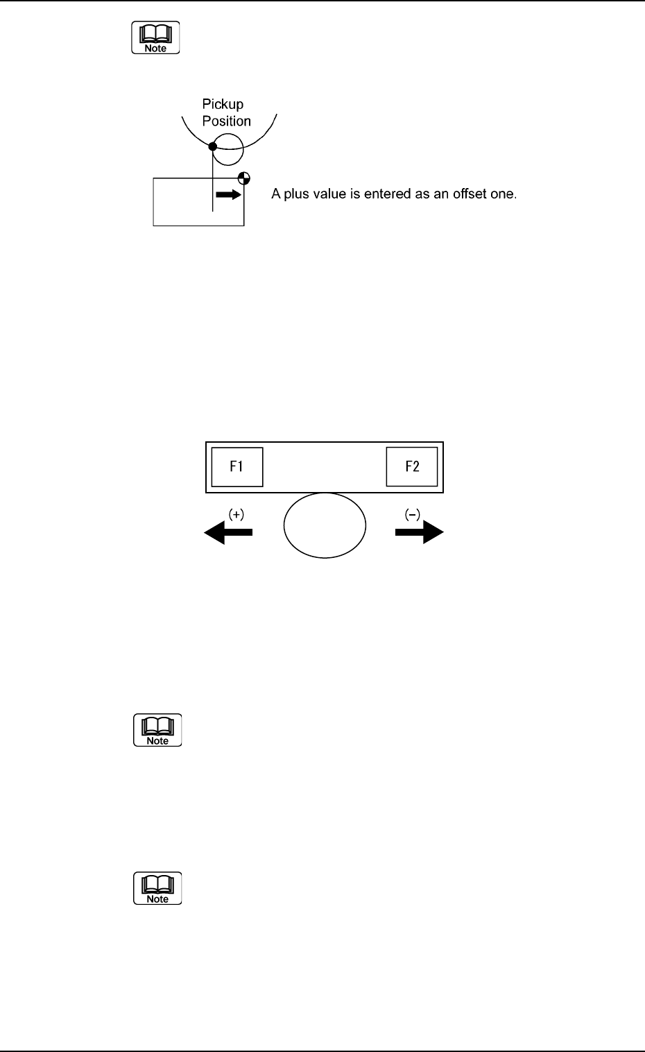
Plus parameters entered in these text boxes increase the
travel of the feeder carriages in the "Fdr. No." direction from
the component pickup position.
Fig. 3E15
*9 Feeder standby position
F1 [mm], F2 [mm]
Shown are the offset values (differences between the values of the feeder
standby position and the actually measured values of the feeder axis origin
position.
Fig. 3E15-1
*10 Input conveyor width [mm]
This is the offset value indicating the difference between P.C.B. Di-
mension Y and the actually measured conveyor width.
The actual value is measured after the conveyor width is
changed when the clearance data and device offset are re-
garded as “0” (zero).
*11 Output conveyor width [mm]
This is the offset value indicating the difference between P.C.B. Di-
mension Y and the actually measured conveyor width.
The actual value is measured after the conveyor width is
changed when the clearance data and device offset are re-
garded as “0” (zero).
0307-006 5-15
AGS01EDTP
3.2 "Device Offset" Tab

0307-006 5-16 AGS01EDTP
*12 X/Y table chute width [mm]
This is the offset value indicating the difference between the chute
width of the X/Y table and the actually measured value.
(a) Measure the actual value at the P.C.B. outlet/input sec-
tions (fixed sections). Do not perform the measure-
ment at the roller position of the slide block.
(b) The actual value should be measured after the con-
veyor width is changed when the clearance data and
device offset are regarded as “0” (zero).
*13 Support pin up/down [mm]
This is the offset value indicating the difference between the P.C.B.
thickness and the length of the support pin (actually measured value).
*14 Unit P.C.B. B.B.R.
X [mm], Y[mm]
This is the offset data used to correct the positional deviation of the
unit P.C.B. B.B.R. detection sensor.
X [mm] : Positional Correction Data in Horizontal Direction
Y [mm] : Positional Correction Data in Vertical Direction
3.2 "Device Offset" Tab