3OM-1054-002.pdf - 第64页
(C02_02) Unit P .C.B. B.B.R. Select one of the following options to determine whether or not the unit P .C.B. B.B.R. function should be used. Disable : The unit P .C.B. B.B.R. function is not used. Enable : The unit P .C…
(C02) Placement Data (P-data)
(C02_01) Unit Control
Select one of the following options to determine whether the selected
placement data (U01, U02, ..... Un) should be used.
In normal cases, select "Placement".
Placement : The placement data of the selected unit (group) be-
comes valid.
Bypass : The placement data of the selected unit (group) be-
comes invalid.
Offset X [mm] and Offset Y [mm]
Set the offset values for all placement coordinates X and Y and the
recognition coordinates of the unit P.C.B. in the placement data (P-
data).
Unit: mm
(a) Use "000.000" (zero) in normal cases.
(b) Note that these offset values do not give any effect to the
coordinates (X [mm] and Y [mm]) of "(A02_02) P.E.C.
recognition mode global".
Offset Z
Set the offset value for all placement angles (Z=Theta) in the place-
ment data (P-data).
Unit: degree
Use "000.00" (zero) in normal cases.
2.5 Placement Data
0303-005 2-44 AGS01EDTP
Placement
Unit Control
Fig. 3B87
Fig. 3B88
Offset X [mm]
Offset Y [mm]
+000.000
+000.000
Fig. 3B89
+000.00
Offset Z [deg]
(C02_02) Unit P.C.B. B.B.R.
Select one of the following options to determine whether or not the unit
P.C.B. B.B.R. function should be used.
Disable : The unit P.C.B. B.B.R. function is not used.
Enable : The unit P.C.B. B.B.R. function (2-point recognition) is
used.
• When "Enable" is set, the recognition coordinates differ as shown
in below (1) and (2) according to the parameter set in the "P.E.C.
recognition mode image" text box (described in (A02_01) P.E.C. rec-
ognition function). Refer to "(A02) P.E.C. Recognition Data" in "2.3
Operation Data".
Options for Image Recognition Mode
(1) "Enable" (Normal Image Recognition Mode)
(2) "U-N" in "P.E.C. recognition mode image" Text Box
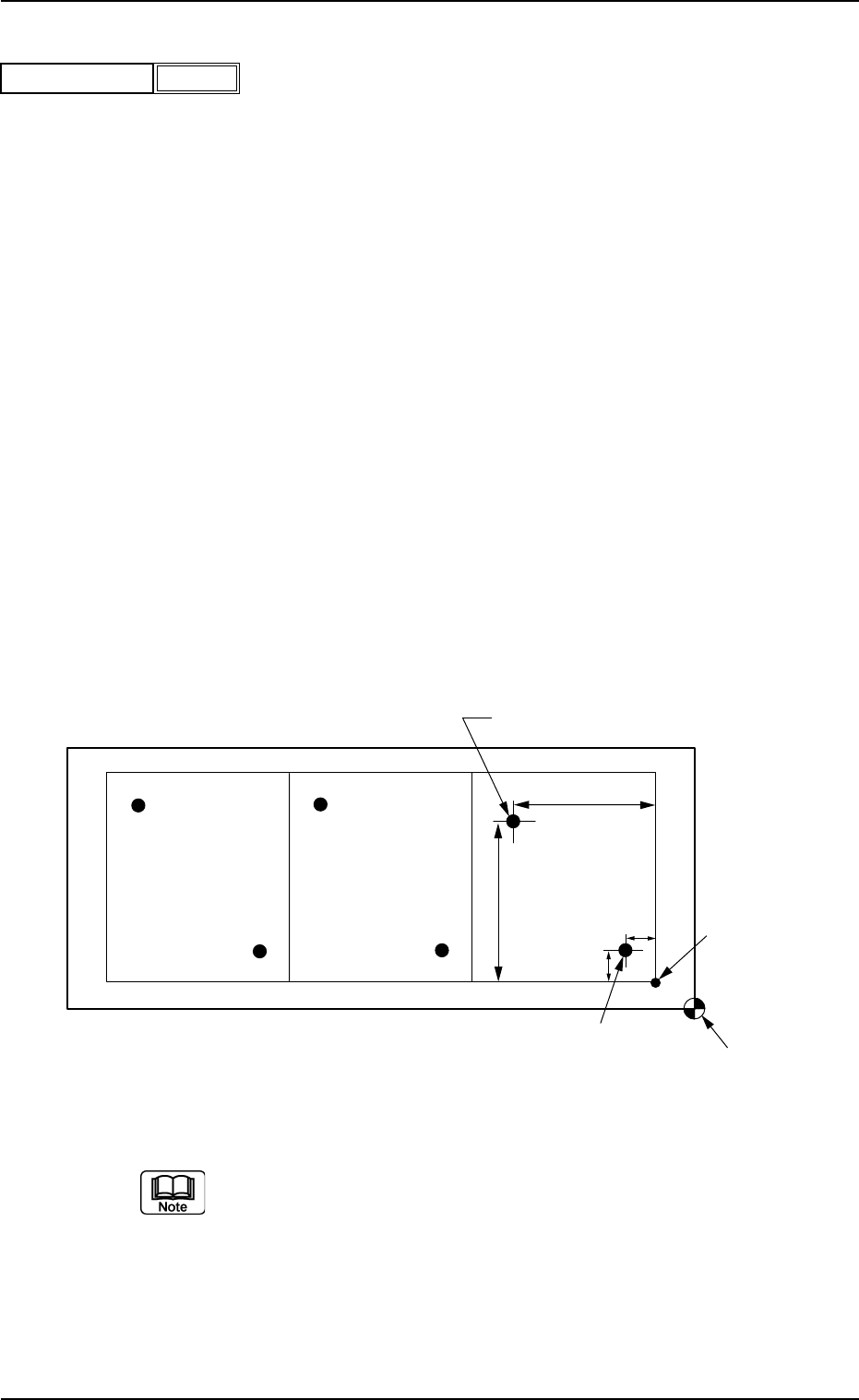
(1) The following is based on the parameter "Enable" (Normal Image Rec-
ognition Mode).
Fig. 3B91 Example of Unit P.C.B. B.B.R. Recognition
(a) Refer to "2. Various Functions" (Section 2) in "Volume 2: Operation
(Supervisor)" for details.
(b) The pattern origin (coordinates) must be located inside the place-
ment coordinate reference point (coordinates).
(c) Determine the coodinates of the first and second fiducial marks for
the unit P.C.B. B.B.R. recognition function.
2.5 Placement Data
0307-005 2-45 AGS01EDTP
Enable
Unit P.C.B. B.B.R.
Fig. 3B90
Placement Coordinate Reference Point
Pattern Origin
Second Fiducial Mark
First Fiducial Mark
Y
2
X
2
Y
1
X
1
Recog Coord X1 [mm] and Recog Coord Y1 [mm]
Set the X1 and Y1 coordinates of the first fiducial mark based on the
pattern origin.
Unit: mm
Recog Coord X2 [mm] and Recog Coord Y2 [mm]
Set the X2 and Y2 coordinates of the second fiducial mark based on
the pattern origin.
Unit: mm
Fiducial Mark FM1 and Fiducial Mark FM2
Set the mark Nos. of the first and second fiducial marks FM1 and FM2.
Select the mark Nos. (Mark #) specified in the P.C.B. recognition mark
data of the operation data.
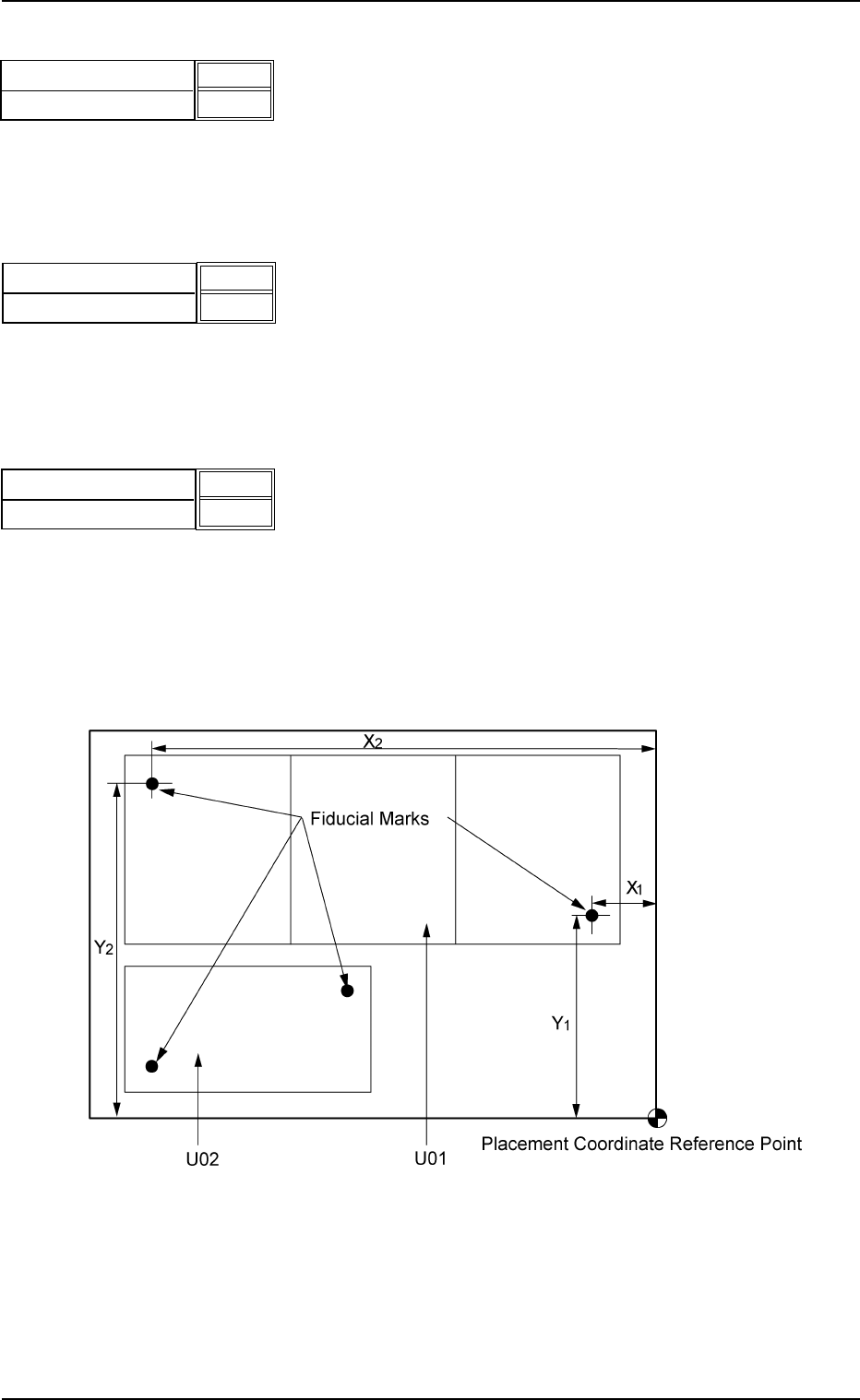
(2) "U-N" in "P.E.C. recognition mode image" Text Box
Fig. 3B94-1 Example of Two Units
• Set parameters in the "Recog Coord X1 [mm]", "Recog Coord Y1
[mm]", "Recog Coord X2 [mm]", "Recog Coord Y2 [mm]", "Fidu-
cial Mark FM1", and "Fiducial Mark FM2" text boxes for each unit.
• The recognition coordinates must be specified, regarding the
placement coordinate reference as an origin.
Recog Coord X1 [mm]
Recog Coord Y1 [mm]
010.000
010.000
Fig. 3B92
Fig. 3B93
Recog Coord X2 [mm]
Recog Coord Y2 [mm]
100.000
100.000
0307-005 2-46 AGS01EDTP
Fig. 3B94
Fiducial Mark FM1
Fiducial Mark FM2
01
01
2.5 Placement Data