3OM-1054-002.pdf - 第266页
0303-005 5-39 AGS01EDTP *10 Camera3 Z = = = = = Theta [deg] This is the offset data used to correct angle difference between the X/Y table coordinate system and the Camera #3 (P .E.C. Recogni- tion Camera) scanning coord…
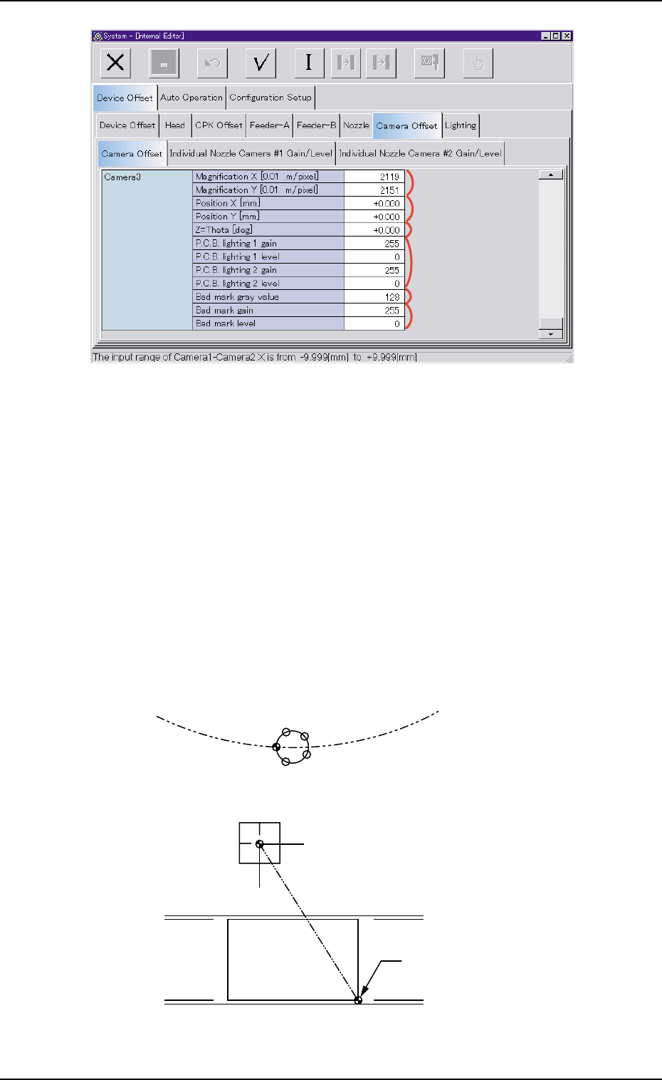
Fig. 3E35-2 "Camera Offset" Tab Sheet (3)
*8 Camera3
Magnification X [0.01
µµ
µµ
µm/pixel], Y [0.01
µµ
µµ
µm/pixel]
These parameters are used to set magnification of Camera #3
(P.E.C. Recognition Camera) in increments of 0.01 µm per pixel.
Parameters must be entered for both X and Y directions.
*9 Camera3
Position X (horizontal) [mm], Y (vertical) [mm]
The distances between the X/Y table P.C.B. origin and the center of
Camera #3 (P.E.C. Recognition Camera) should be set to adjust
the data compared with the design values.
Fig. 3E35-3
3.2 "Device Offset" Tab
P.C.B. Origin
Rotary Turret
P.E.C. Recognition Camera
P.C.B.
0307-006 5-38 AGS01EDTP
µ
µ
*8
*10
*9
*13
*12
*11
0303-005 5-39 AGS01EDTP
*10 Camera3
Z
= =
= =
= Theta [deg]
This is the offset data used to correct angle difference between the
X/Y table coordinate system and the Camera #3 (P.E.C. Recogni-
tion Camera) scanning coordinate system.
When the camera scanning coordinate system deviates
counterclockwise from the X/Y table coordinate system, a
plus value must be entered as offset data.
*11 Camera3
P.C.B. lighting 1 gain, P.C.B. lighting 1 level,
P.C.B. lighting 2 gain, P.C.B. lighting 2 level
These parameters are used to set amplifications at which the im-
age signals of Camera #3 (P.E.C. Recognition Camera) is converted
into picture information representing brightness.
(a) The lower the gain is, the better the contrast becomes.
(b) The smaller the level is, the brighter the whole view
becomes.
*12 Camera3
Bad mark gray value
This parameter is used to set the contrast of the bad mark.
*13 Camera3
Bad mark gain, Bad mark level
These parameters are used to set amplifications at which the im-
age signals of the bad mark is converted into picture information
representing brightness.
(a) The lower the gain is, the better the contrast becomes.
(b) The smaller the level is, the brighter the whole view
becomes.
3.2 "Device Offset" Tab
(2) "Individual Nozzle Camera #1 Gain/Level" and "Individual
Nozzle Camera #2 Gain/Level" Tabs
• Sheet Layout
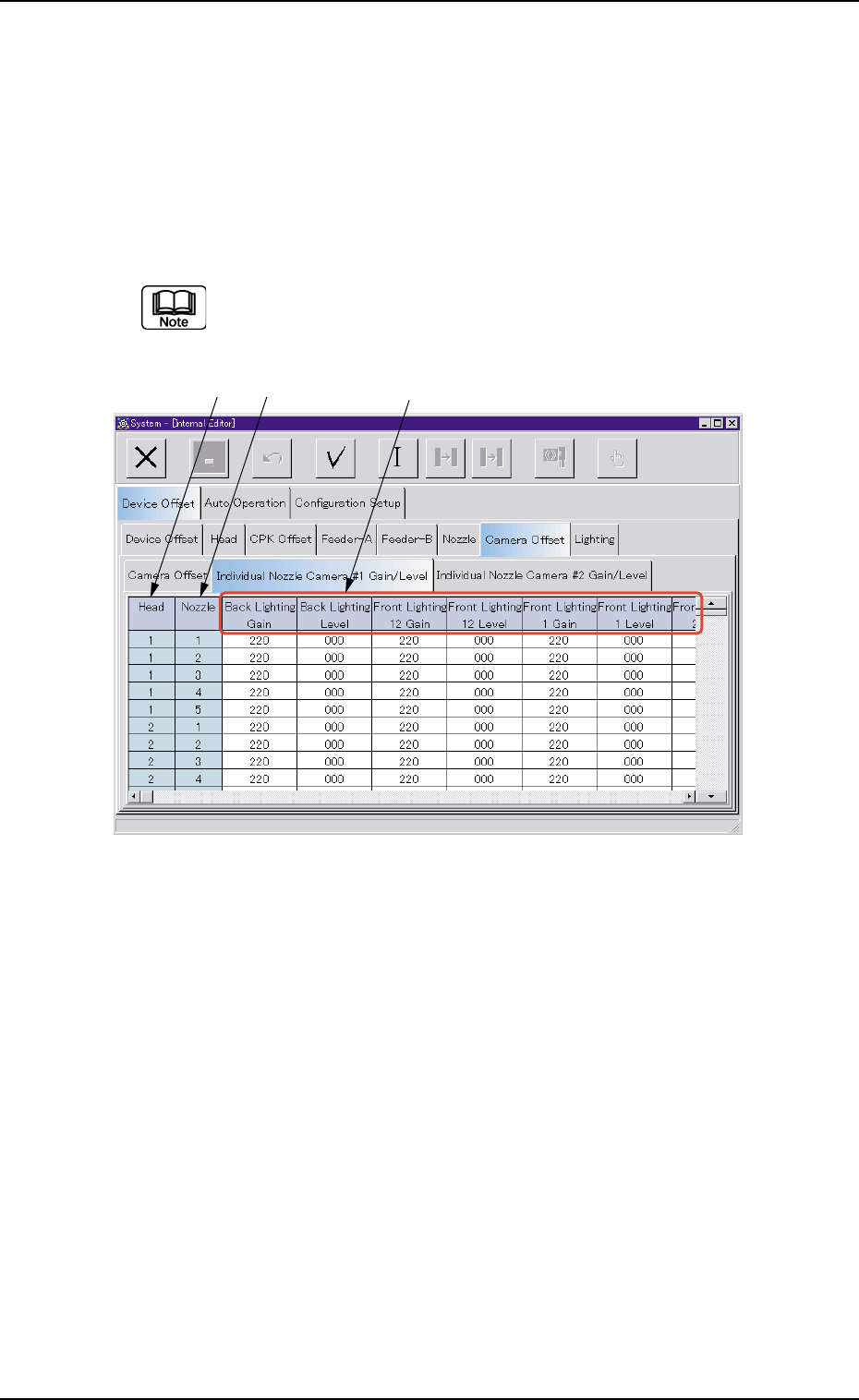
When the "Individual Nozzle Camera #1 Gain/Level" tab is pressed in
the "Device Offset" tab sheet, the following tab sheet appears.
In case of the "Individual Nozzle Camera #2 Gain/Level" tab
sheet, follow almost the same navigations.
Fig. 3E36 "Individual Nozzle Camera #1 Gain/Level" Tab Sheet
• Sheet Composition
*1 Head
The head Nos. are displayed.
*2 Nozzle
The nozzle Nos. are displayed.
0303-005 5-40
AGS01EDTP
*1
*3
*2
3.2 "Device Offset" Tab