3OM-1054-002.pdf - 第58页
(A04) Setup Data Fig. 3B70 Edit Window (Example) Unless "Enable" is selected for a device to be set up, the machine does not perform any setup operation on the device. (A04_01) L conveyor Set "Disable"…
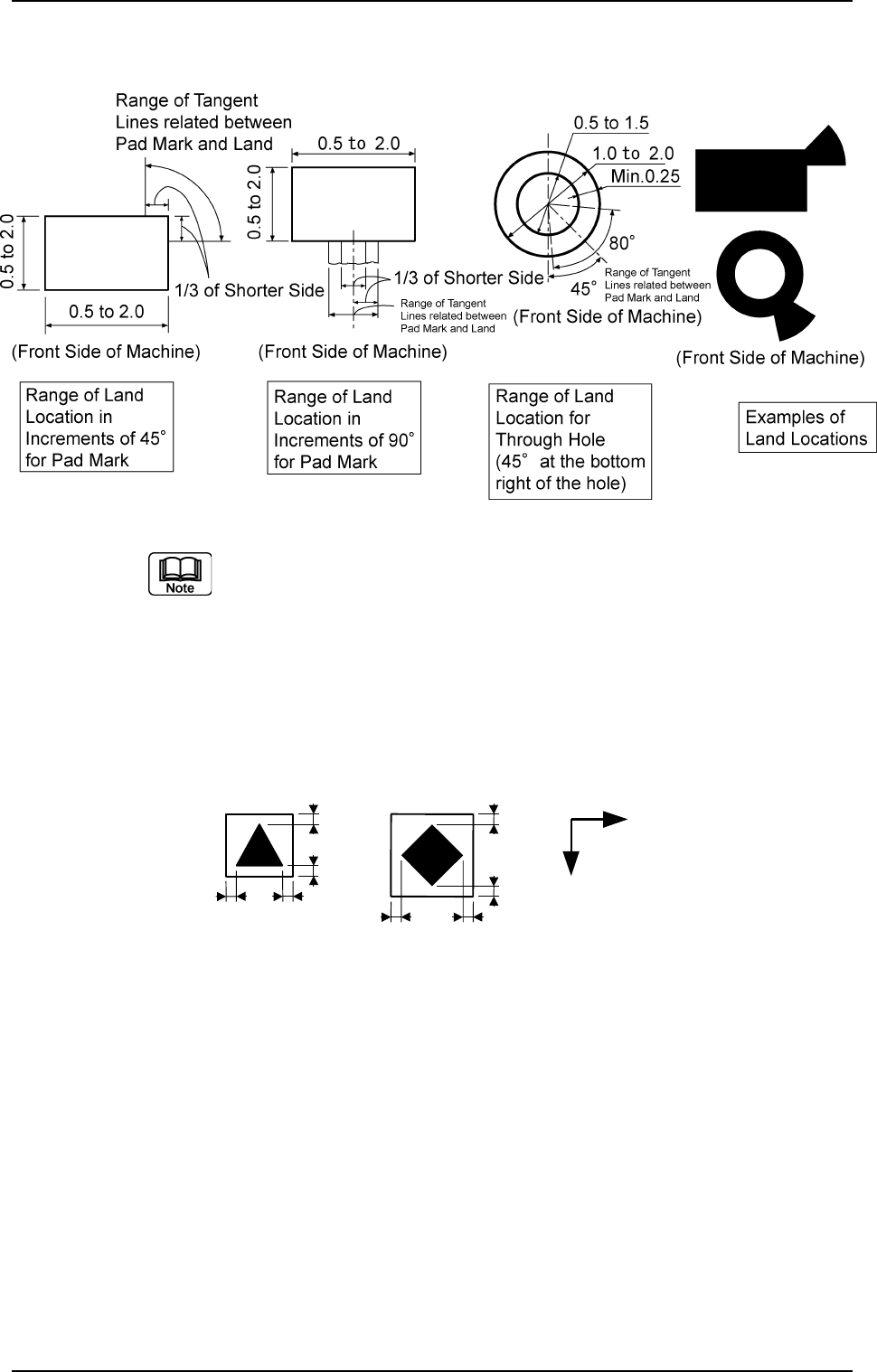
(4) Specifications of Lines extended from a Pad Mark or a Through Hole
Unit: mm
Fig. 3B68
(a) A through hole or a pad mark should have only one land
which is directed in increments of 45°.
Consult our marketing department or sales agency for
details (dimensions, etc.).
(b) A copper leaf, a resist, a coating, a silk print, and a punched hole
should not exist in the range of 1.0 mm in both X and Y directions
from the outermost edges of a fiducial mark. They may cause
false recognition.
Example:
(Front Side of Machine)
Unit: mm
Fig. 3B69
(c) The shape of P.C.B. (a cutout, a punched hole) and the
external elements (light reflected from a structure, light
emitted from an external device, etc.) may sometimes in-
terfere with recognition of the fiducial marks. Consult our
marketing department or sales agency for details.
(d) A fiducial mark should make ample contrast with the sur-
roundings. (To prevent false recognition)
(e) Anything resembling a pattern similar to a fiducial mark
should not exist in the designated window. If one exists, it
may cause false recognition.
(f) A test may be required when the fiducial mark cannot be
recognized because of the extreme warpage of the P.C.B.
2.3 Operation Data
0307-005 2-38 AGS01EDTP
1.0
1.0
1.0
1.0
1.0
1.0
1.0
1.0
Y
X
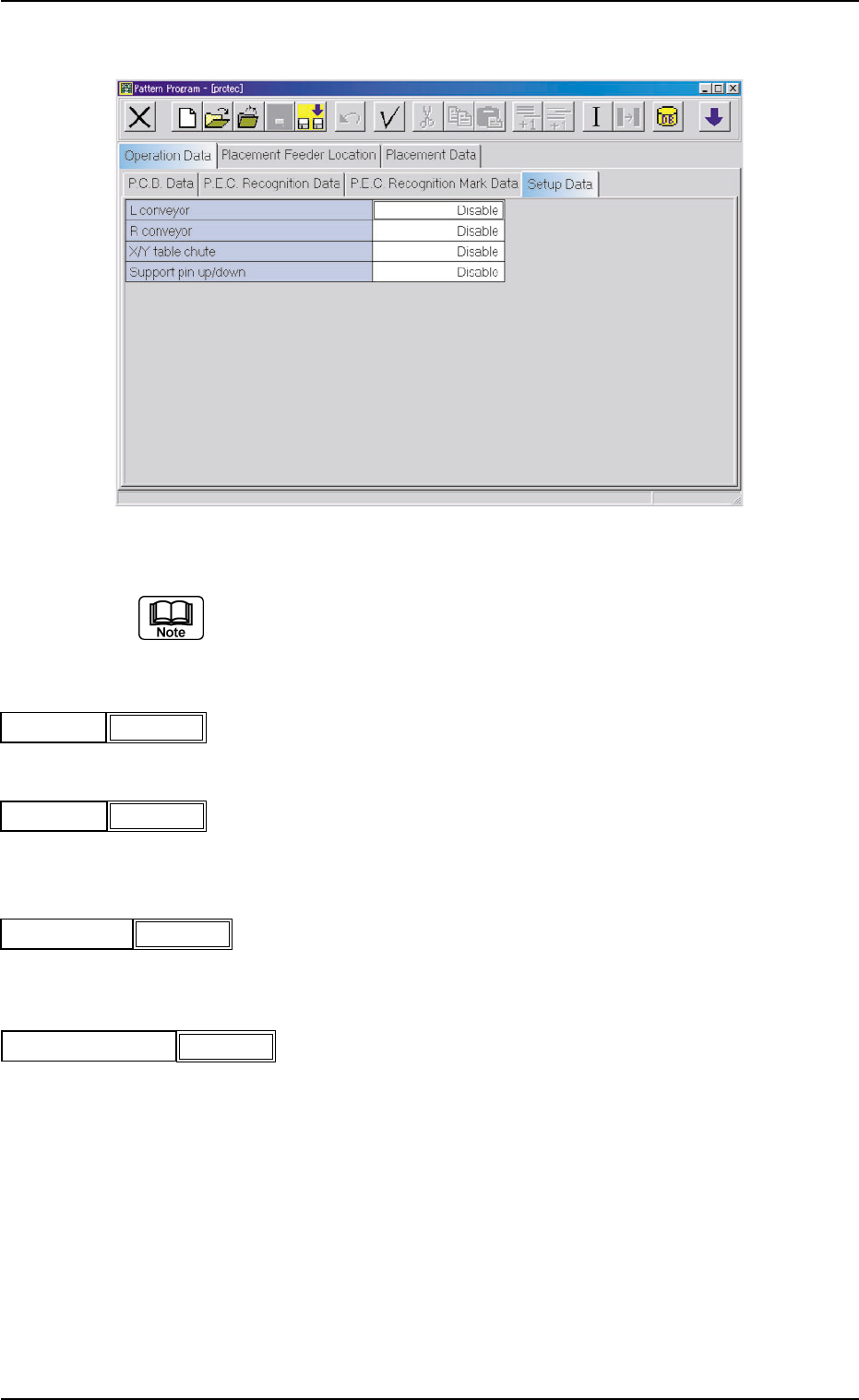
(A04) Setup Data
Fig. 3B70 Edit Window (Example)
Unless "Enable" is selected for a device to be set up, the machine does
not perform any setup operation on the device.
(A04_01) L conveyor
Set "Disable" or "Enable" in the text box.
(A04_02) R conveyor
Set "Disable" or "Enable" in the text box.
(A04_03) X/Y table chute
Set "Disable" or "Enable" in the text box.
(A04-04) Support pin up/down
Set "Disable" or "Enable" in the text box.
2.3 Operation Data
021 1-004 2-39 AGS01EDTP
Disable
L conveyor
Fig. 3B71
R conveyor
Fig. 3B72
Disable
X/Y table chute
Fig. 3B73
Disable
Support pin up/down
Fig. 3B74
Disable
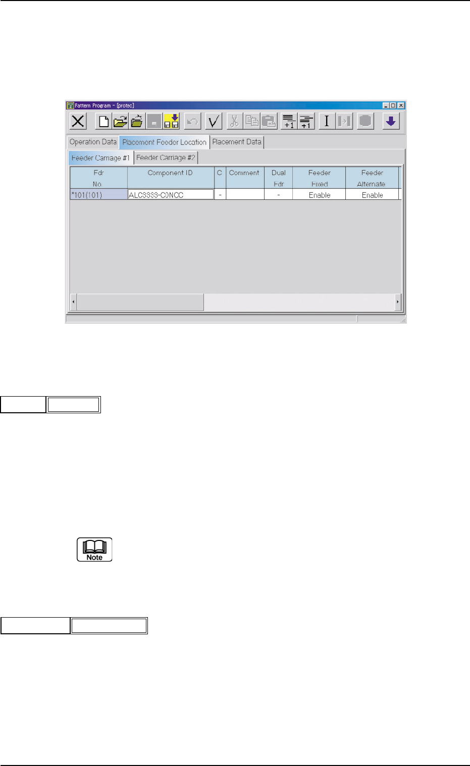
2.4 Placement Feeder Location Data
(B01) Feeder Carriage #1, #2
Each parameter must be set for the feeder carriages to be used.
Fig. 3B77 Edit Window (Example)
(B01_01) Fdr No.
Shown are the feeder Nos. in the placement feeder location data.
The numbers in ( ) indicate the feeder Nos. that will actually be loaded
with components.
Data Input Range
Feeder Carriage #1: 101 to 159
Feeder Carriage #2: 201 to 259
The numbers in ( ) indicate the feeder Nos. where the feeder No. offset in
the operation data is added.
(B01_02) Component ID
Set component IDs in the text boxes.
2.4 Placement Feeder Location Data
021 1-004 2-40 AGS01EDTP
101(101)Fdr No.
Fig. 3B78
C1005T05B0---
Component ID
Fig. 3B79