3OM-1054-002.pdf - 第34页
(A01_03) P .C.B. origin offset X (horizontal) [mm] and Y (vertical) [mm] Set the offset values to correct the difference between the placement coordinate reference point (N 0 ) and the P .C.B. origin (P 0 ). Unit: mm &qu…
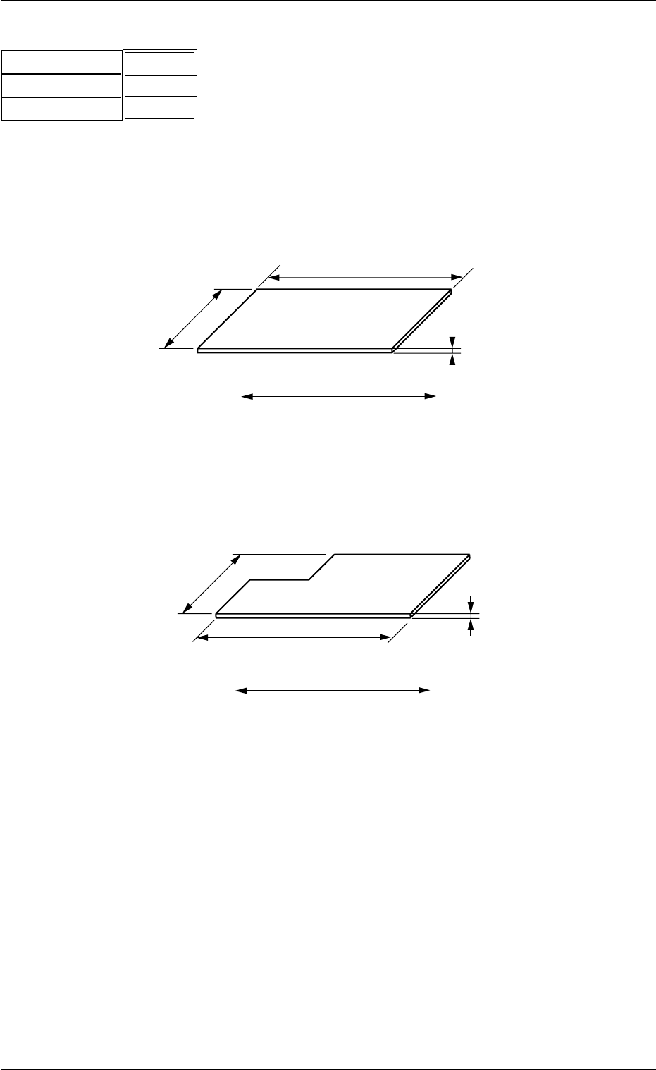
(A01_02) P.C.B. size
X (horizontal) [mm], Y (vertical) [mm], and T (thickness)
[mm]
Set the dimensions of the P.C.B. to be produced.
Unit: mm
Fig. 3B10
When the P.C.B. has a cutout, the following dimensions must
be entered.
Fig. 3B11
Data Input Range
X: 50 to 330 Y: 50 to 250 T: 0.5 to 5.0
330.000
250.000
1.600
X (Horizontal)[mm]
Y (Vertical)[mm]
T (Thickness)[mm]
Fig. 3B9
2.3 Operation Data
021 1-004 2-14 AGS01EDTP
P.C.B.
P.C.B. Flow Direction
Y (Vertical)
X (Horizontal)
T (Thickness)
Y (Vertical)
X (Horizontal)
T (Thickness)
P.C.B.
P.C.B. Flow Direction
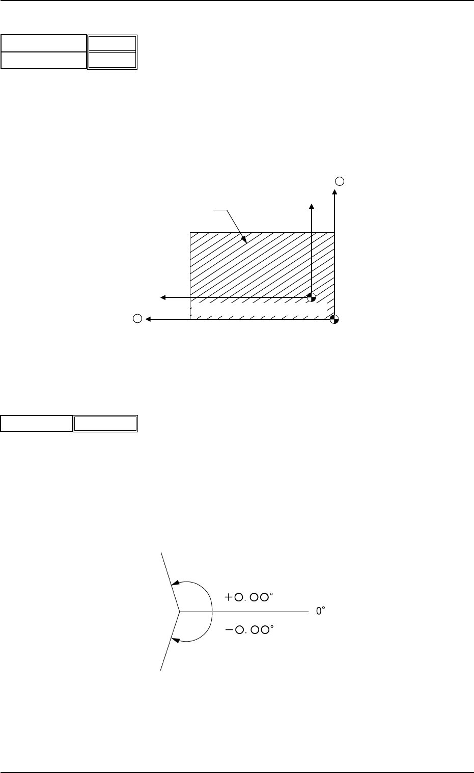
(A01_03) P.C.B. origin offset
X (horizontal) [mm] and Y (vertical) [mm]
Set the offset values to correct the difference between the placement
coordinate reference point (N
0
) and the P.C.B. origin (P
0
).
Unit: mm
"Plus" or "Minus" can be set in both X and Y coordinates in the direc-
tion of the correction.
Fig. 3B13 Example of "+" (Plus) Direction for Correction
Z=(Theta)[deg]
Set the offset value for component placement angle.
The set value is added to the "Z=theta" of all components in the place-
ment data (P data).
To correct the angle of component placement counterclockwise, a
parameter must be entered with a "+" (plus) sign. Put a "-" (minus)
sign to correct it clockwise.
Unit: degree
Fig. 3B15
P.C.B. Origin(P0)
X +
Y +
P.C.B.
Placement Coordinate Reference(N
0
)
Fig. 3B12
2.3 Operation Data
0303-005 2-15 AGS01EDTP
X (horizontal)[mm]
Y (vertical)[mm]
+00.000
+00.000
Z=Theta [deg]
Fig. 3B14
+0.00
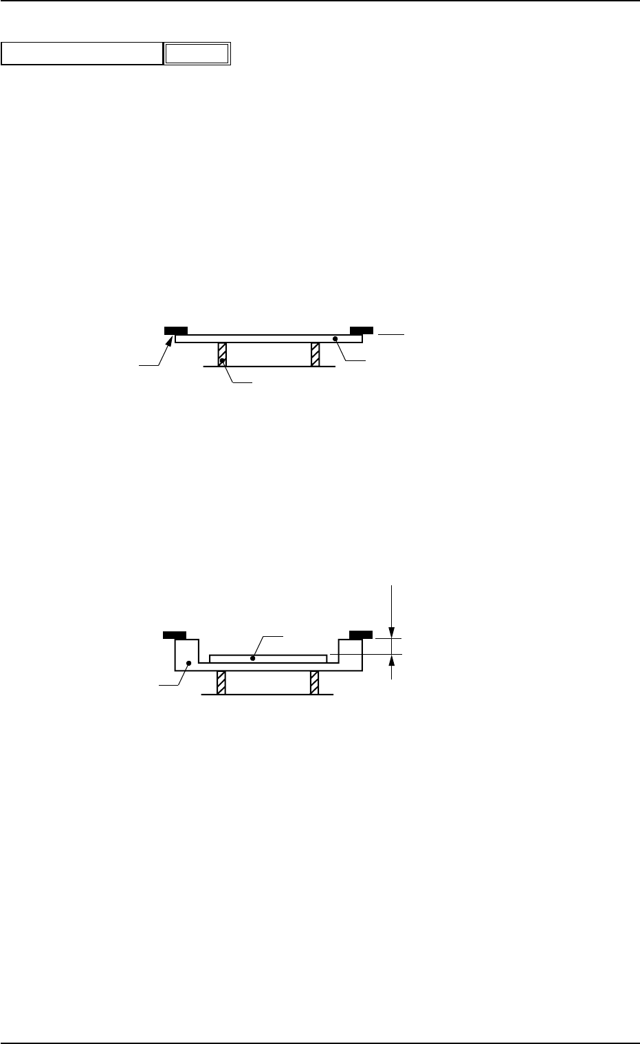
(A01_04) P.C.B. height offset
Set an offset value as a nozzle descending distance based on the
upper surface of the P.C.B. in the component placement section.
This offset value applies to all components in the pattern program.
Unit: mm
Normal Cases
Set "0.000 mm" (zero) in the text box.
The figure below shows that the upper surface of a P.C.B. is main-
tained at the P.C.B. upper surface reference point by the P.C.B. sup-
port pins.
Fig. 3B17
Example of Jig P.C.B. Usage
The figure below shows that the upper surface of a P.C.B. is lower
than the P.C.B. upper surface reference point.
If "+a mm" is set as an offset value at this time, components can be
placed correctly on the P.C.B.
Fig. 3B18
P.C.B. Upper Surface
Reference Plane
P.C.B.
Chute
P.C.B. Support Pin
P.C.B.
Jig P.C.B.
a mm
P.C.B. Upper Surface
Reference Plane
0303-005 2-16 AGS01EDTP
2.3 Operation Data
+
0.00
P.C.B. height offset [mm]
Fig.3B16