3OM-1054-002.pdf - 第240页
*7 Feeder carriage connection 1-2 [mm] This is the offset data used to adjust the space between the two feeder carriages when connected. Reserved Data *8 Feeder carriage 1 X (Horizontal) [mm], Y (V ertical) [mm], L (Heig…
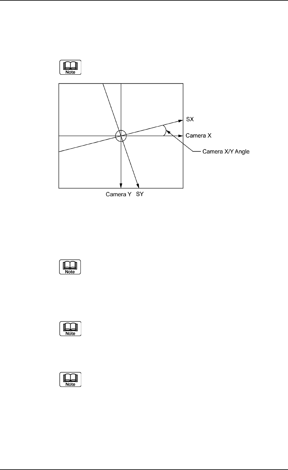
*2 Camera X [deg], Y [deg]
This is the offset data for angle difference between the camera X
and Y axis and the scanning coordinates X and Y of the component
recognition camera (Camera 1: high magnification).
The parameters are computed using the jig nozzle.
Fig. 3E13
*3 Component pickup (Z) axis [mm]
This is the offset data for the origin position of the component pickup
Z axis (CZ).
A plus (+) value increases the downward movement of the
nozzle.
*4 Component placement (Z) axis [mm]
This is the offset data for the origin position of the component place-
ment Z axis (MZ).
A plus (+) value increases the downward movement of the
nozzle.
*5 P.C.B. transfer Left [mm], Right [mm]
This is the offset data to adjust the feed limit at P.C.B. transfer.
This offset data is used for fine adjustment of the transfer
stroke.
*6 Master nozzle H [mm], L-L [mm], L-X [mm], L-Y [mm]
Entered are the nozzle parameters that were measured using the
master nozzle.
H:Height (H Level)
L-L : Height (L Level)
L-X : X in L Level
L-Y : Y in L Level
0303-005 5-13
AGS01EDTP
3.2 "Device Offset" Tab
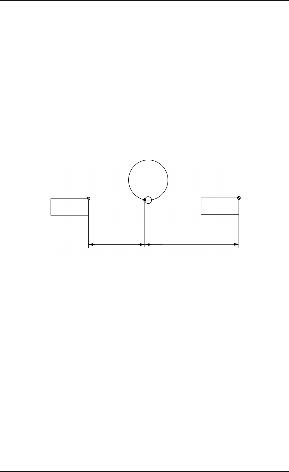
*7 Feeder carriage connection 1-2 [mm]
This is the offset data used to adjust the space between the two
feeder carriages when connected.
Reserved Data
*8 Feeder carriage 1 X (Horizontal) [mm], Y (Vertical) [mm], L
(Height) [mm], 2 X (Horizontal) [mm], Y (Vertical) [mm], L (Height)
[mm]
This is the offset data used to adjust the positional distances be-
tween the component pickup position and the feeder carriages.
X [mm] (Horizontal) : Horizontal Position Data
Y [mm] (Vertical) : Vertical Position Data
L [mm] (Height) : Pickup Height Position Data
Fig. 3E14
0307-005 5-14
AGS01EDTP
3.2 "Device Offset" Tab
Pickup
Position
Feeder Carriage #2
FDR. 201 at Origin
Feeder Carriage #1
FDR. 101 at Origin
#2
#1
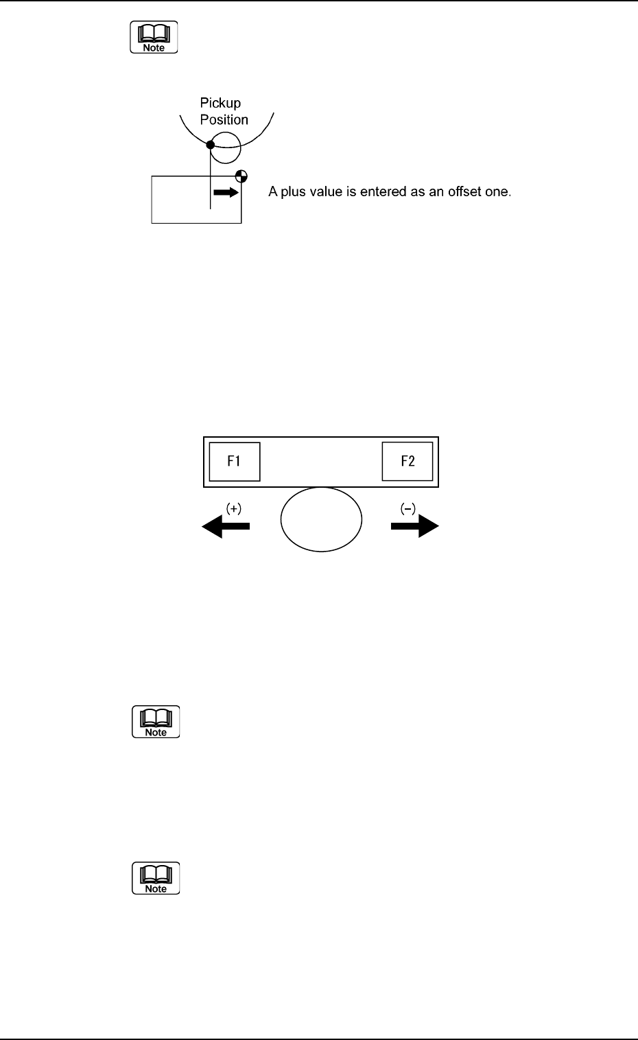
Plus parameters entered in these text boxes increase the
travel of the feeder carriages in the "Fdr. No." direction from
the component pickup position.
Fig. 3E15
*9 Feeder standby position
F1 [mm], F2 [mm]
Shown are the offset values (differences between the values of the feeder
standby position and the actually measured values of the feeder axis origin
position.
Fig. 3E15-1
*10 Input conveyor width [mm]
This is the offset value indicating the difference between P.C.B. Di-
mension Y and the actually measured conveyor width.
The actual value is measured after the conveyor width is
changed when the clearance data and device offset are re-
garded as “0” (zero).
*11 Output conveyor width [mm]
This is the offset value indicating the difference between P.C.B. Di-
mension Y and the actually measured conveyor width.
The actual value is measured after the conveyor width is
changed when the clearance data and device offset are re-
garded as “0” (zero).
0307-006 5-15
AGS01EDTP
3.2 "Device Offset" Tab