3OM-1054-002.pdf - 第75页
(C03_06) B-X [mm], B-Y [mm] When "Enable" is set in the "Unit P .C.B. B.B.R." text box, it is required to set the coordinates of each unit P .C.B. B.B.R. mark (each bad mark) based on the placement co…
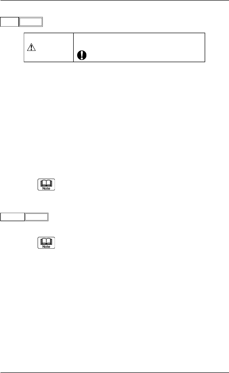
(C03_04) C
Enter some of the following control commands.
CAUTION
If a control command other than the following ones is
used, the step becomes invalid.
- (hyphen): This command handles the steps as those for compo-
nent placement.
S:This command invalidates the steps specified as those
for component placement.
C:This command invalidates the steps specified as those
for component placement.
Note : As for dispensers, these steps become valid.
D:This command handles the steps as those for compo-
nent placement.
Note : As for dispensers, these steps become invalid.
E:When placement data (O) is not created, this shows
the end of the steps in the placement data (P).
Confirm that "0" (zero) is set in the "X [mm]", "Y [mm]", "Z=theta", "B-X
[mm]", and "B-Y [mm]" and set "E".
(C03_05) Comment
Set a comment for each step No.
Up to 32 characters (alphanumerics and marks) can be used.
The automatic operation is not affected by these comments.
2.5 Placement Data
021 1-004 2-55 AGS01EDTP
Fig. 3B112
-
C
-
Comment
Fig. 3B113
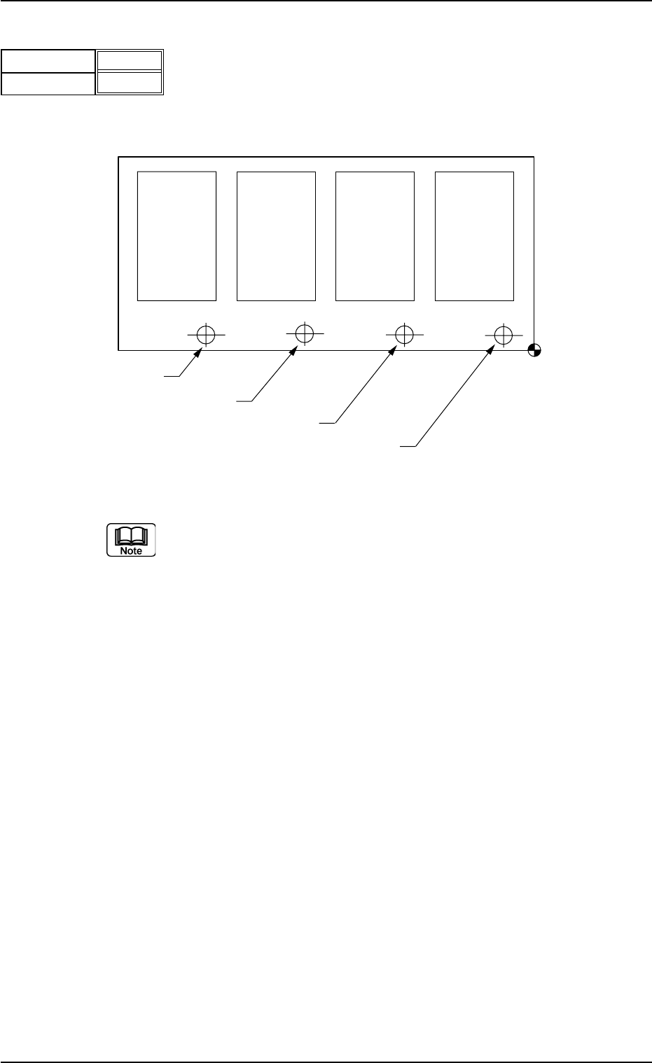
(C03_06) B-X [mm], B-Y [mm]
When "Enable" is set in the "Unit P.C.B. B.B.R." text box, it is required
to set the coordinates of each unit P.C.B. B.B.R. mark (each bad mark)
based on the placement coordinate reference N
0
.
Unit: mm
Fig. 3B115
(a) Refer to "2. Various Functions" in "Section 2" of "Volume 2: Opera-
tion (Supervisor)" for the unit P.C.B. B.B.R. detection function.
(b) Do not set any coordinates in the text boxes of the last line (last step
No.).
Keep them as "000.000".
Placement Coordinate
Reference (N
0
)
Bad Mark of Pattern 1
Bad Mark of Pattern 2
Bad Mark of Pattern 3
Bad Mark of Pattern 4
Pattern 4
(B-X
4
, B-Y
4
)
Pattern 3
(B-X
3
, B-Y
3
)
Pattern 2
(B-X
2
, B-Y
2
)
Pattern 1
(B-X
1
, B-Y
1
)
2.5 Placement Data
021 1-004 2-56 AGS01EDTP
Fig. 3B114
B-X [mm]
B-Y [mm]
000.000
000.000
3. Example of Pattern Program Creation
Described on the following pages are the examples of pattern programs
to be created.
• Single Pattern
• Single Pattern (P.E.C. Recognition Function Enabled)
• Repetitive Patterns
• Repetitive Patterns (Unit P.C.B. B.B.R. Enabled)
• Repetitive Patterns (Unit P.C.B. B.B.R. Function Enabled)
• Repetitive Patterns (Block Sorting Enabled)
• Repetitive Patterns (Polar Coordinate Conversion Function)
• Multi-Model Repetitive Patterns
3.1 Single Pattern
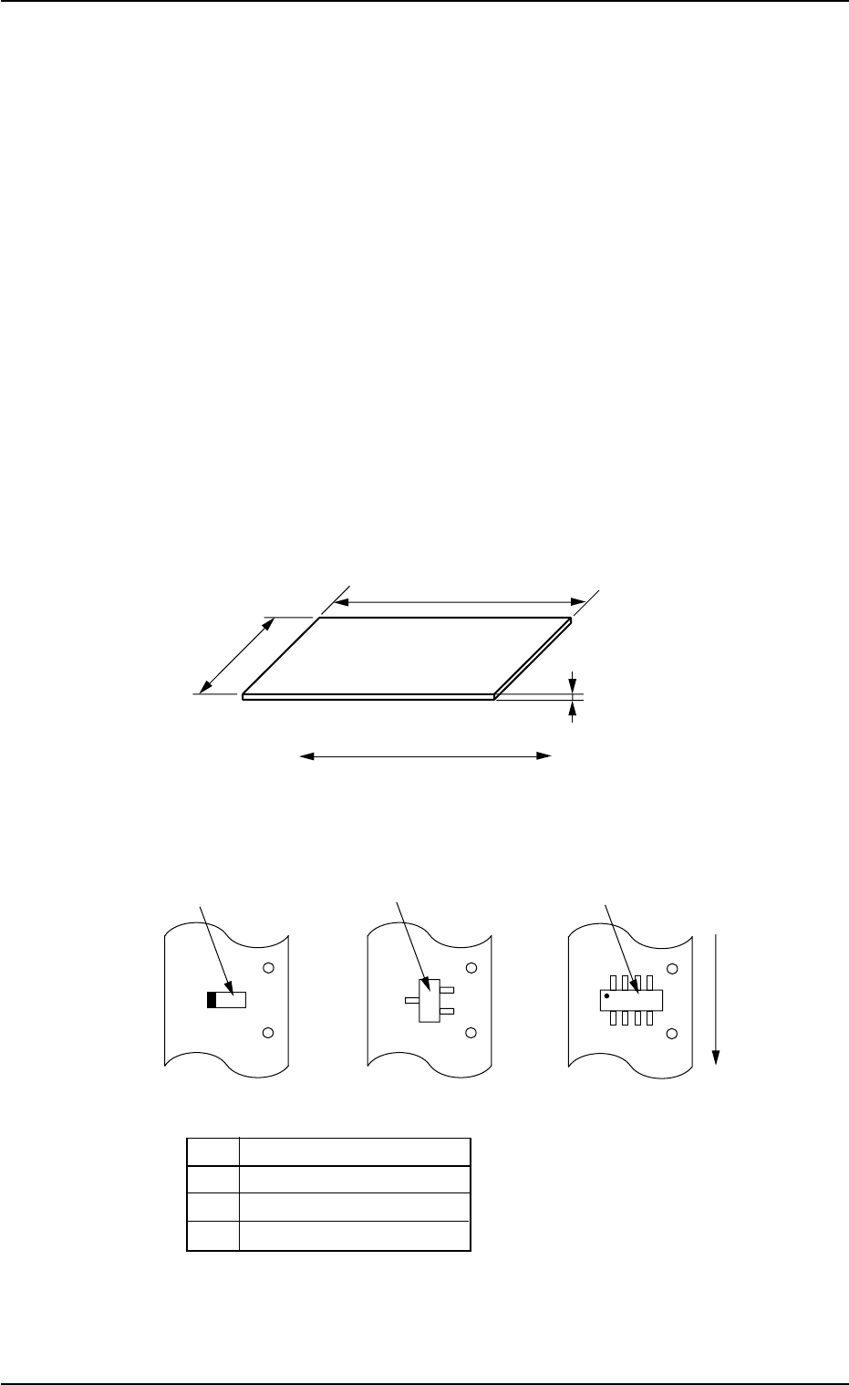
(1) Information on Pattern Program Creation
• P.C.B. Size
Fig. 3B116
• Packaged Posture and IDs of Components
No. Component ID
*1 TANA3216B0- - -
*2 TR2012-3B0SANL2
*3 SOP008-B02SAN
Fig. 3B117
01 12-003 2-57 AGS01EDTP
3. Example of Pattern Program Creation
250 mm
1.6 mm
P. C.B .
330 mm
P.C.B. Flow Direction
*3
*2
*1
User Direction of
Component Feed