3OM-1054-002.pdf - 第59页
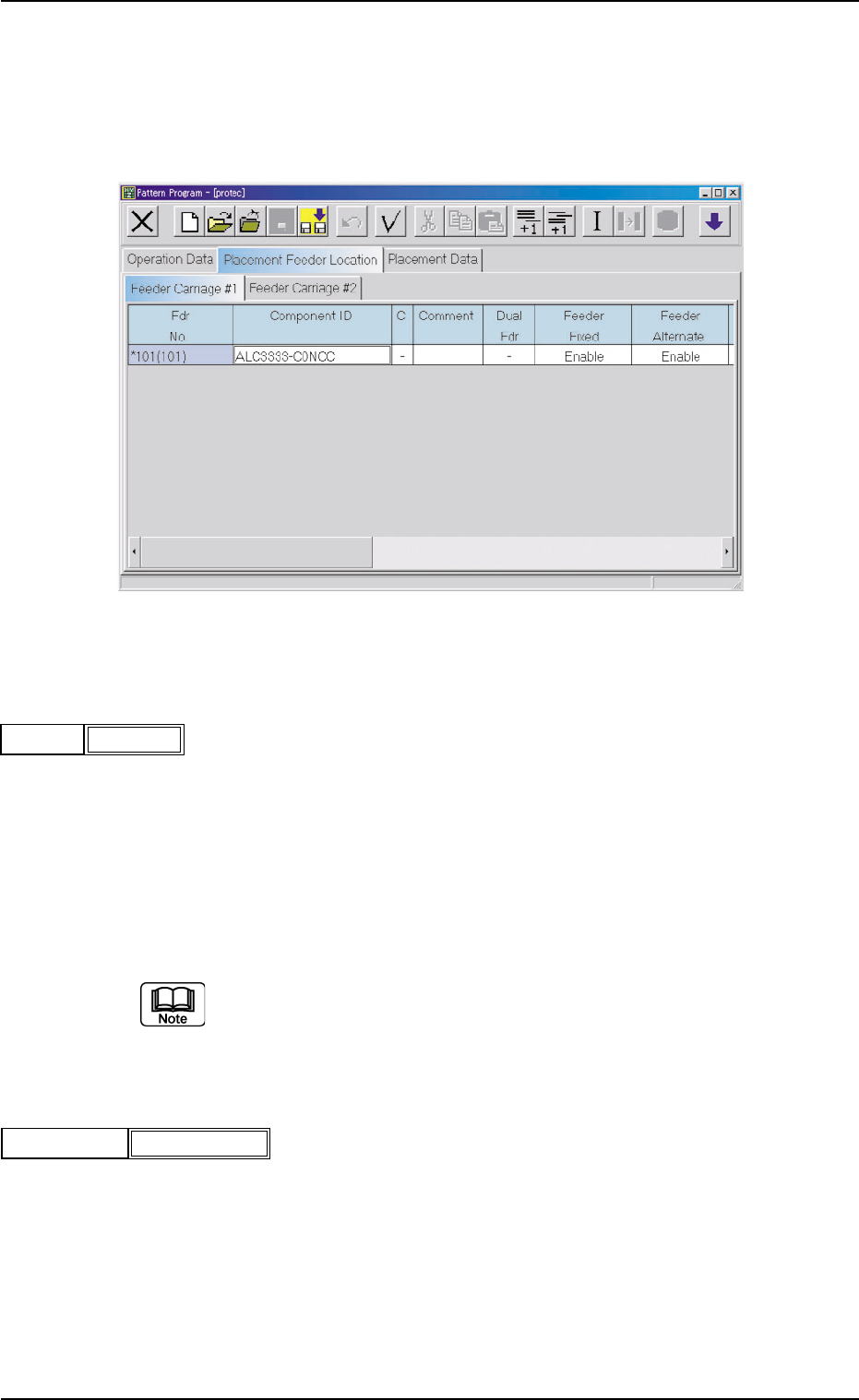
2 . 4 Placement Feeder Location Data (B01) Feeder Carriage #1, #2 Each parameter must be set for the feeder carriages to be used. Fig. 3B77 Edit Window (Example) (B01_01) Fdr No. Shown are the feeder Nos. in the placemen…
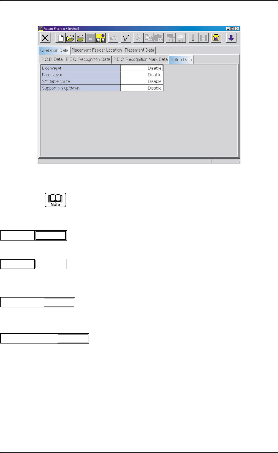
(A04) Setup Data
Fig. 3B70 Edit Window (Example)
Unless "Enable" is selected for a device to be set up, the machine does
not perform any setup operation on the device.
(A04_01) L conveyor
Set "Disable" or "Enable" in the text box.
(A04_02) R conveyor
Set "Disable" or "Enable" in the text box.
(A04_03) X/Y table chute
Set "Disable" or "Enable" in the text box.
(A04-04) Support pin up/down
Set "Disable" or "Enable" in the text box.
2.3 Operation Data
021 1-004 2-39 AGS01EDTP
Disable
L conveyor
Fig. 3B71
R conveyor
Fig. 3B72
Disable
X/Y table chute
Fig. 3B73
Disable
Support pin up/down
Fig. 3B74
Disable
2.4 Placement Feeder Location Data
(B01) Feeder Carriage #1, #2
Each parameter must be set for the feeder carriages to be used.
Fig. 3B77 Edit Window (Example)
(B01_01) Fdr No.
Shown are the feeder Nos. in the placement feeder location data.
The numbers in ( ) indicate the feeder Nos. that will actually be loaded
with components.
Data Input Range
Feeder Carriage #1: 101 to 159
Feeder Carriage #2: 201 to 259
The numbers in ( ) indicate the feeder Nos. where the feeder No. offset in
the operation data is added.
(B01_02) Component ID
Set component IDs in the text boxes.
2.4 Placement Feeder Location Data
021 1-004 2-40 AGS01EDTP
101(101)Fdr No.
Fig. 3B78
C1005T05B0---
Component ID
Fig. 3B79
(B01_03) C
Set control commands in the text boxes.
If a control command other than the following ones is
used, the step becomes invalid.
- (hyphen) : This command handles the steps as those for the
placement feeder location data.
E:This command shows the end of the placement feeder
location data.
The step where "E" is set is valid.
S:This command invalidates the steps specified as place-
ment feeder location data.
X:This command invalidates the steps specified as place-
ment feeder location data and shows the end of the
data.
(B01_04) Comment
A comment can be entered for each feeder No. (Fdr No.).
Up to 32 characters (alphanumerics and marks) can be used.
(a) The performance of the machine is not affected by these comments.
In other words, it has nothing to do with or without these comments.
(b) It is recommended to set helpful information on components related
to the feeder Nos. (Fdr Nos.).
(B01_05) Dual Fdr
Select one of the following options as the data for the dual tape feeder.
-:The dual tape feeder is not used.
A: Components are picked up from Side A of the dual tape feeder.
B: Components are picked up from Side B of the dual tape feeder.
(B01_06) Feeder Fixed
Select "Enable" or "Disable" to determine whether or not the feeder
positions should be fixed in place.
When "Enable" is selected, the feeder No. (Fdr No.) and the compo-
nent ID are not affected by any insert and delete operations of a com-
ponent.
Disable : The feeder position is not fixed.
Enable : The feeder position is fixed.
2.4 Placement Feeder Location Data
0307-005 2-41 AGS01EDTP
Comment
Fig. 3B81
-
C
Fig. 3B80
Feeder Fixed
Fig. 3B82
Disable
Dual Fdr
Fig. 3B81-1
-
CAUTION